Now we know the stepper motors required for our project we can match them to a suitable CNC controller. The controller converts the g-code we’ve created and sends step pulses to the stepper motors. It also takes input signals from the machine such as limit switches and E-stops.
So there are 3 things we need to know:
Number of Axes. So usually 3 for routers and 4 for a foam cutter Current and voltage we need to supply to the stepper motors How do we intend to connect the computer to the CNC controller Number of Axes CNC routers can use 3 or 4 axis controllers. There is only 3 planes of movement X, Y and Z but some designs use two stepper motors on one axis. My OX CNC router uses two NEMA 23 on the Y-Axis as its a gantry type router. Some move the table bed for the Y-Axis on sliders and only need 1 motor for the Y-Axis. Like a 3d printer bed.
Y-Axis complete and running very smooth
Foam cutters need 4 axes to allow the hot wire to move in any direction on 4 planes usually X,Y,U and V.
Generally, you are going to need at last NEMA23 from 175oz/in upwards unless your machine is very small such as a CNC engraver. These are quite often used for making Printed Circuit Boards(PCB) and if you check the description they will say only for soft materials.
For routers, the cutting material plays a big part in our decision. Harder materials will need a more powerful stepper because the cutting bit is being driven into the material.
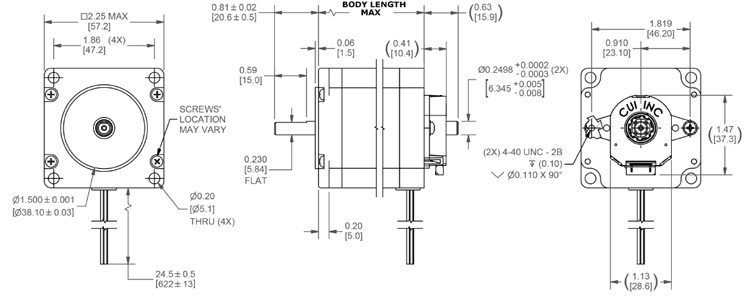
The WorkBee from Ooznest in the UK which is based on the OpenBuilds design. It uses NEMA23 of 175 oz/in. If you check some of the offerings on eBay for 6040 CNC routers you’ll quite often see in the description 57 size motors, which is the metric equivalent of 2.3 inches or NEMA23’s and these usually come with 175-200oz-in motors
If you intended to cut very hard materials then high torque steppers motors will be required usually around 300-400 oz/in and you may need to go up to NEMA34 and you will need a strong frame to support that.
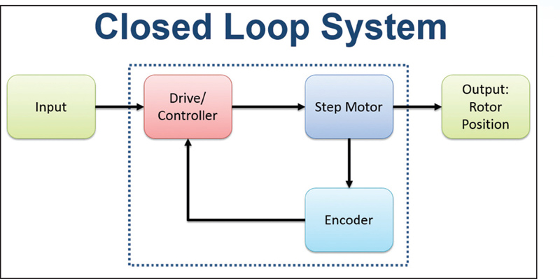
Step motors are widely used in automation due to their high resolution, precision positioning, minimal control electronics, and low cost. As an open loop system, traditional step motors are driven without the need for sensors to feed information back to a controller; however, the open loop configuration of step motors has challenges.
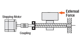
Position Verification — When pushed beyond its limits, a step motor will stall before reaching the endpoint. This event typically occurs when motors are not adequately specified for high-cycle applications. An encoder can provide position feedback at the end of the motion profile, indicating if the step motor stopped before reaching the end position. The controller compares the encoder counts that define the actual motor position to the target motor position at the end of a move to determine if there is a difference. If the encoder counts don’t match to the actual motor position, a corrective move or motion profile is calculated and executed.
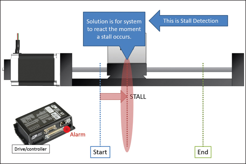
Stall Detection — Stall detection notifies the user/system/machine as soon as a motor stall occurs, eliminating the uncertainty of whether or not the motor reached its target position. A more advanced function than position verification, stall detection (Figure 2) enables the controller to compare the registers of the encoder counts and target motor position on a continuous basis instead of just at the end of the move.
Stall Prevention— While greatly increasing system functionality, stall detection does not inherently improve step motor performance; it still requires the operator to perform a corrective move and re-reference the axis to the home position. Stall prevention, on the other hand, dynamically and automatically adjusts the move profile to prevent a stall, enabling the motor to operate with constant torque to get into an accurate end position without stalling.
Servo Control and Increased Motor Torque — Using stepper motor encoder feedback to servo-control, a step motor increases motor torque for greater dynamic performance. With peak torques up to 50% higher than the rated holding torque of the motor, the servo-controlled step motor system can operate at higher acceleration rates and with higher throughput for faster machine cycles.
When using a stepper motor, integrating an incremental encoder is relatively straightforward. Still, there are some general guidelines to consider.
Incremental encoders (like any stepper motor encoder) all function as part of a feedback system — providing closed-loop operation. Using information from the encoder, the drive system alters motor operation.
However, incremental encoders don’t keep track of position once power is lost. They also need a reference position to return to every time upon startup.
Keep this in mind when using and driving a stepper motor, because the machine design must set to a reference position when using incremental encoders.
Incremental encoders are often useful when speed control requirements are part of a system. If there’s less concern over the position of the shaft — and more of a concern over how fast it is moving — then the fact that incremental encoders don’t track position once off is less critical. In fact, here their simple operation and low price benefit the design.
Incremental encoders keep track of speed where only the difference between two positions is necessary.
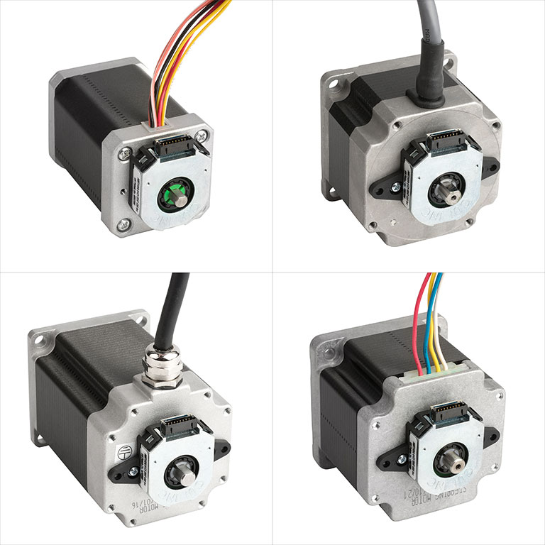
There are a few different methods to mount an encoder to a stepper motor. Each of them is useful for various situations, and the choice depends on the motion system.
Incremental encoders with shaft mounting … A coupling connects the encoder to the shaft. This creates mechanical and electrical isolation, but also adds cost because the coupling is an extra part and because this method requires a longer motor shaft.
Incremental encoders with a hub or hollow-shaft setup … The encoder directly mounts to the motor using a spring-loaded tether. This is a design that is easy to install and requires no alignment. The only caveat is that this geometry requires careful electrical isolation.
Incremental encoders with a bearingless or ring mount … Here, the sensor is in the form of a ring that mounts to the motor’s surface. A wheel mounts to the motor’s shaft. There are useful for heavy-duty applications.
Nema 17 motor is not standard for electrical characteristics of the stepper motor. It is just faceplate and mounting holes standard to make it easier to interchange motors. Most likely you have to check from the specification that what is rated current for that motor and is it unipolar or bipolar one. Choose driver based on that.
Note: Drive can always be more powerful than the motor, but you have to limit your current from the drive side. It’s also possible to use chopper drives with the less current rating, but then your motor runs underpowered.
But one can definitely make assumptions on the motor size that NEMA 17 could use 1A – 2A current and NEMA 23 motor could use around 2A – 5A current.
Final words This articles scope was to make a high-level overview of how to drive a stepper motor. I hope I delivered and you have now a better understanding of this topic and can start experimenting.
Now the real fun and learning begins.
There is a lot more than these basic concepts I introduced. There will be problems with vibration, torque, cooling motors, choosing hardware, missing steps, calculating steps and configuring software. Stepper motor projects are prone to problems because of all dependencies in the chain. Starting from hardware or power to bad configuration or just wrong program. Basic debugging skills are very handy here and it helps to have extra components to switch in case of hardware malfunction.
Did I answer all basic questions? Or I missed some crucial concept that left you wondering? Let me know about it in the comments. I would be grateful to know so I can improve this article.
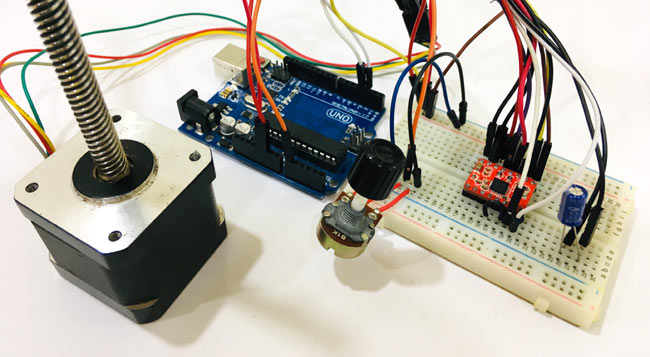
Circuit diagram to control Nema17 stepper motor with Arduino is given in the above image. As A4988 module has a built-in translator that means we only need to connect the Step and Direction pins to Arduino. Step pin is used for controlling the steps while the direction pin is used to control the direction. Stepper motor is powered using a 12V power source, and the A4988 module is powered via Arduino. Potentiometer is used to control the direction of the motor.
If you turn the potentiometer clockwise, then stepper will rotate clockwise, and if you turn potentiometer anticlockwise, then it will rotate anticlockwise. A 47 µf capacitor is used to protect the board from voltage spikes. MS1, MS2, and MS3 pins left disconnected, that means the driver will operate in full-step mode.
Complete connections for Arduino Nema 17 A4988 given in below table.
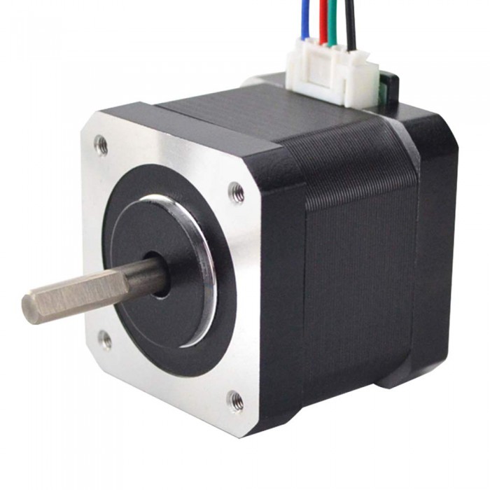
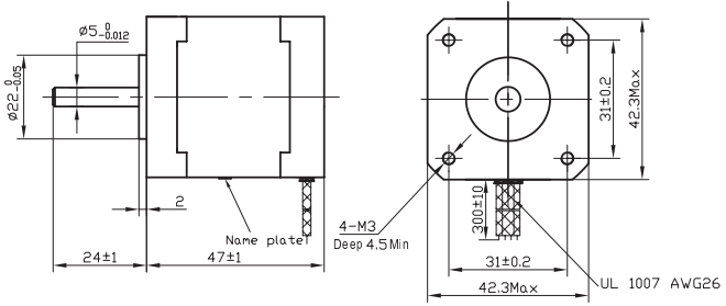
NEMA 17 is a hybrid stepping motor with a 1.8° step angle (200 steps/revolution). Each phase draws 1.2 A at 4 V, allowing for a holding torque of 3.2 kg-cm. NEMA 17 Stepper motor is generally used in Printers, CNC machines and Laser Cutters.
NEMA17 Stepper Motor is commonly used in CNC machines, Hard Drives and Linear Actuators. The motor have 6 lead wires and rated voltage is 12 volt. It can be operated at lower voltage but torque will drop. These motors has a step angle of 1.8 deg., this means that it has 200 steps per revolution for every step it will cover a 1.8° hence the level of control is also high. These motors run on 12V and hence can provide high torque. So if you are looking for a compact easy to use stepper motor with high torque then this motor is the right choice for you.
Operation of Nema17 is similar to normal Stepper Motors. NEMA 17 stepper motor has a 1.7 x 1.7-inch faceplate, and it usually has more torque than the smaller variants, such as NEMA 14. This motor has six lead wires, and the rated voltage is 12 volt. It can be operated at a lower voltage, but torque will drop. Stepper motors do not rotate they step, and NEMA17 motor has a step angle of 1.8 deg. means it covers 1.8 degrees in every step. Wiring diagram for NEMA17 is given below.
Stepper Motor Applications CNC machines Precise control machines 3D printer/prototyping machines (e.g. RepRap) Laser cutters Pick and place machines
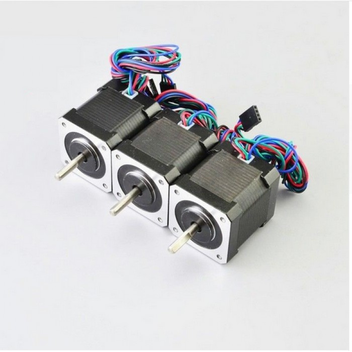
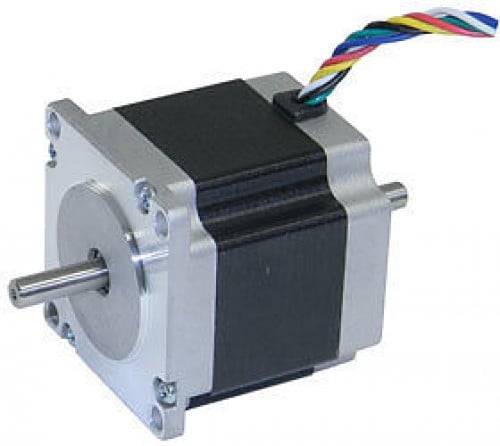
NEMA 23 is a high torque hybrid bipolar stepper motor
with a 2.3×2.3 inch faceplate. This motor has a step angle of 1.8 deg.,
this means that it has 200 steps per revolution and for every step it
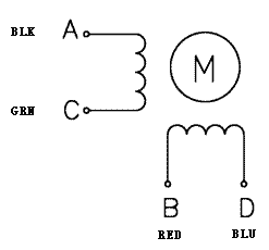
will cover 1.8°. The motor has four colour coded wires (Black, Green,
Red & Blue) terminated with bare leads. Black and Green wire is
connected with one coil; Red and Blue is connected with other. This
motor can be controlled by two H-bridges but it is recommended to use a
stepper motor driver.
How to use NEMA 23 Stepper Motor
As mentioned above this stepper motor draws high current so instead of
controlling it directly using H-bridges, use an appropriately powerful
stepper motor driver. To know how to make this motor rotate we should
look into the coil diagram below.
As you can see from above diagram this motor has four wires in
different colours. This motor can be made to rotate only if the coils
are energized in a logical sequence. This logical sequence can be
programmed using a microcontroller or by designing a digital circuit.
Stepper Motor Applications
CNC machines
Precise control machines
3D printer/prototyping machines (e.g. RepRap)
Laser cutters
Pick and place machines
The automation aspect of certain types of systems and equipment will depend on the type of stepper motor that you use. NEMA hybrid stepper motors are recommended if you want a versatile stepper motor that can work with most industrial automation requirements. The technology behind NEMA stepper motors, like the NEMA 23 stepper motors, is far advanced because of its precision and high-torque design.
Speed and torque are the two most crucial
factors when choosing the right stepper motor for automation. NEMA hybrid
stepper motors are preferred in industrial automation because they provide more
power than the lower end models. NEMA 23, in particular, is a recommended
hybrid stepper motor due to its powerful torque and speed, both of which are
essential factors that can improve the performance and reliability of automated
equipment and systems.
A NEMA hybrid stepper motor can be useful
in making semiconductors. It can be complicated to manufacture semiconductors
due to the high amount of output that is involved in the processes. Hence, it
is important for the automation system to be reliable for robotics control,
measurement, inspection, and quality assurance.
One feature of stepper motors that differentiates them from other motor types—particularly servo motors—is that they exhibit holding torque. This means that when the windings are energized but the rotor is stationary, the motor can hold the load in place. But a stepper motor can also hold a load in place when there is no current applied to the windings (for example, in a power-off condition). This is commonly known as the detent torque or residual torque.
Detent torque Stated another way, detent torque is the amount of torque the motor produces when the windings are not energized. The effect of detent torque can be felt when moving the motor shaft by hand, in the form of torque pulsations or cogging.
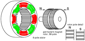
Of the three types of best stepper motors from china—variable reluctance, permanent magnet, and hybrid—only variable reluctance motors do not exhibit detent torque. This is due to the difference in construction between variable reluctance motors versus permanent magnet and hybrid designs. Both permanent magnet and hybrid stepper motors use a permanent magnet rotor, which is attracted to the poles of the stator even when there is no power to the stator windings. Variable reluctance motors, on the other hand, use a passive (non-magnetized) rotor made of soft iron; therefore, there is no attraction between the rotor and the stator when the stator windings are not energized. Hybrid stepper motors incorporate teeth on the surface of the rotor, so they are able to better manage the magnetic flux between the stator and rotor, which gives them higher holding, dynamic, and detent torque values than permanent magnet steppers.
Holding torque A nema 23 stepper motor’s holding torque is the amount of torque needed in order to move the motor one full step when the windings are energized but the rotor is stationary. Holding torque is one of the primary benefits that stepper motors offer versus servo motors and makes steppers a good choice for cases where a load needs to be held in place.
Holding torque is typically higher than running torque, and is limited primarily by the maximum current that the motor can withstand. From a practical standpoint, holding torque is the sum of the magnetic force exerted by the coils to hold the motor’s current position, plus the detent torque. Once the motor is moving, the torque available at low speeds equals the holding torque minus two times the detent torque (because the motor has to work against the detent torque).