How do Hybrid Stepper Motor Work?
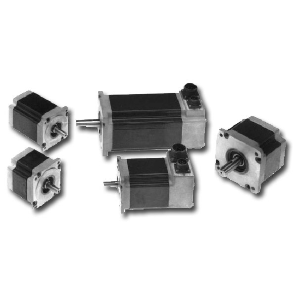
Hybrid stepper motors are a type of motor that combines the functions of both a step motor and a servo motor. The hybrid stepper is used in applications such as robot arms and industrial valves.
Step motors are typically used for continuous rotation, while servo motors are used for precise positioning. Hybrid steppers combine these two functions into one device, which allows them to be more efficient than either design on their own.
Hybrid steppers use an electromagnetic torque armature to transform electrical energy into mechanical energy. This allows them to be very powerful and accurate when moving at high speeds or for low speeds with large loads.
5 Ways to Take Advantage of a Hybrid Stepper Motor
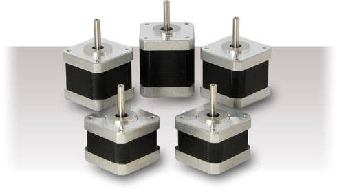
Stepper motors are the most common type of electric motors in robotics, automation, and industrial applications. They are suitable for tasks such as positioning, moving and rotating.
With a hybrid stepper motor, you can get more power with less weight and space. This is because it combines the benefits of both stepper motors and DC brushless motors.
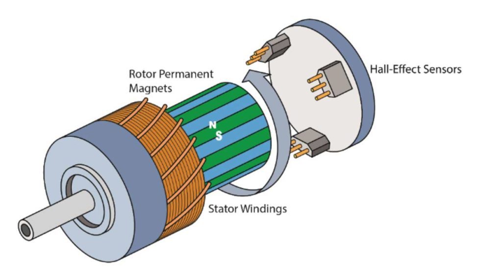
The hybrid stepper motor has three phases: stator, rotor, and rotor-stator coupling. The stator is made up of two or more electromagnets that generate a magnetic field that interacts with the rotor to produce torque. The rotor is made up of a permanent magnet that rotates around an axis while sliding past the stator electromagnets on either side.
The Benefits of Using a Hybrid Stepper Motor
Stepper motors are a type of electric motor that is used in industrial applications and in the automotive industry. They are typically used to drive linear motion and they have high torque output.
Hybrid stepper motors are a type of stepper motor that has both rotary and linear components. They offer the best of both worlds – higher torque output and higher speed capability than traditional stepper motors, but at the same time, lower price point than other types of electric motors.
Companies who use hybrid stepper motors can reduce their operating costs by up to 20%. This is because they require less energy to operate compared with other types of electric motors.