1.The defination of servo motors
A servo motor is an electric motor that converts electrical power into mechanical power. It’s commonly used in dynamic systems where fast movements are required. To achieve this, the servo motor needs to have low inertia or mass and possess high force or torque for acceleration. These requirements impact the design and construction of the servo motor. Low inertia is achieved in a rotating servo motor by employing a slender rotor or a flat “pancake” rotor design. High torque can be attained by using powerful permanent magnets.
2.The history of servo motors
Since the 80s of the 20th century, with the development of integrated circuits, power electronics technology and AC variable speed drive technology, permanent magnet AC servo drive technology has developed prominently. AC servo system has become the main development direction of contemporary high-performance servo system, so that the original DC servo is facing the crisis of being eliminated. After the 90s, the AC servo system that has been commercialized in various countries around the world is a fully digitally controlled sine wave motor servo drive. The development of AC servo drives in the field of transmission is changing with each passing day.
3.Main types of servo motors
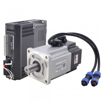
First is the AC servo motor. This type of servo is currently used today by most companies. AC servo motors are mostly used in industrial fields. AC servo motors are AC motors that rely on encoders. These types of servo motors work through controllers providing feedback and closed-loop control. They are known to function at a high accuracy and are easily controllable.
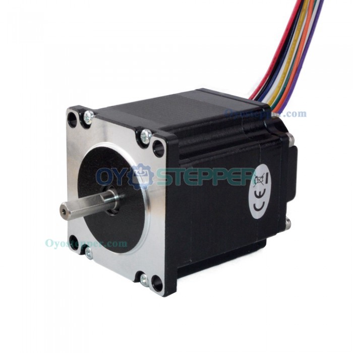
Second is the DC servo motor. These kind of servo motors were used in the past by Fuji Electric but are rarely used nowadays, as AC servo motors are easier to use, more effective, advanced, and reliable.
4.The advantages of servo motors
High efficiency
High output power relative to their size
More constant torque at higher speed
Closed-loop control
Highly reliable and acceleration
High ratio of torque to inertia
High-speed performance
Torque control
Smooth running
High accuracy
Well suited to varying load applications
In conclusion
In the grand symphony of automation, the AC servo motor stands as a virtuoso performer, harmonizing precision and power in a seamless blend.
.jpg)
.png)