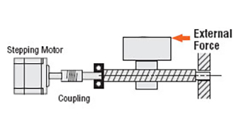
Step motors are widely used in automation due to their high resolution, precision positioning, minimal control electronics, and low cost. As an open loop system, traditional step motors are driven without the need for sensors to feed information back to a controller; however, the open loop configuration of step motors has challenges.
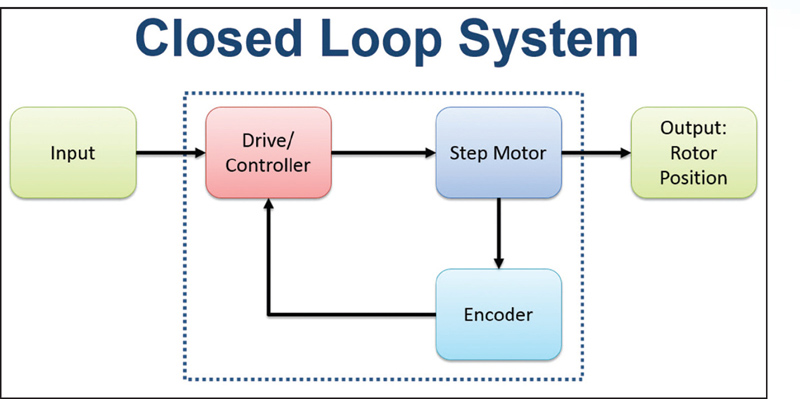
Position Verification — When pushed beyond its limits, a step motor will stall before reaching the endpoint. This event typically occurs when motors are not adequately specified for high-cycle applications. An encoder can provide position feedback at the end of the motion profile, indicating if the step motor stopped before reaching the end position. The controller compares the encoder counts that define the actual motor position to the target motor position at the end of a move to determine if there is a difference. If the encoder counts don’t match to the actual motor position, a corrective move or motion profile is calculated and executed.
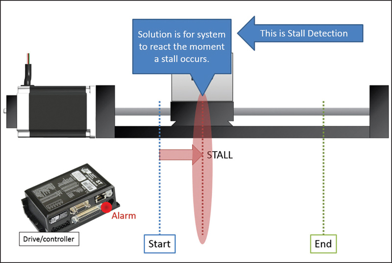
Stall Detection — Stall detection notifies the user/system/machine as soon as a motor stall occurs, eliminating the uncertainty of whether or not the motor reached its target position. A more advanced function than position verification, stall detection (Figure 2) enables the controller to compare the registers of the encoder counts and target motor position on a continuous basis instead of just at the end of the move.
Stall Prevention— While greatly increasing system functionality, stall detection does not inherently improve step motor performance; it still requires the operator to perform a corrective move and re-reference the axis to the home position. Stall prevention, on the other hand, dynamically and automatically adjusts the move profile to prevent a stall, enabling the motor to operate with constant torque to get into an accurate end position without stalling.
Servo Control and Increased Motor Torque — Using stepper motor encoder feedback to servo-control, a step motor increases motor torque for greater dynamic performance. With peak torques up to 50% higher than the rated holding torque of the motor, the servo-controlled step motor system can operate at higher acceleration rates and with higher throughput for faster machine cycles.