Key specifications and considerations of geared stepper motor

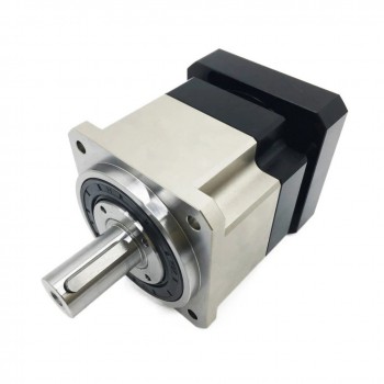
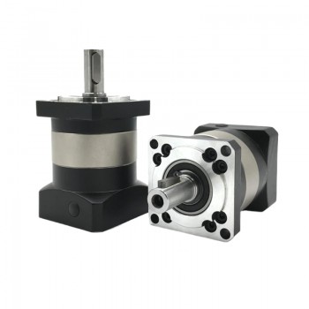
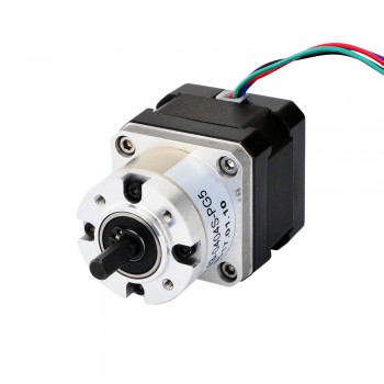
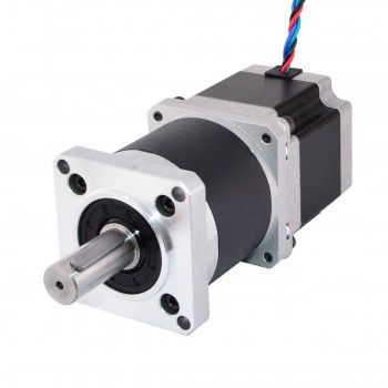
1.What is a geared stepper motor?
A geared stepper motor combines a standard stepper motor with a gearbox (gear reduction unit), integrating precise step-based motion with mechanical advantages to provide high torque and low speed from a single unit, ideal for applications needing powerful, accurate positioning without feedback, like robotics or 3D printers. The gearbox reduces rotational speed while multiplying output torque, with planetary or spur designs being common.

2.Basic working principle of geared stepper motor
The core principle behind a gear motor is simple mechanics: gears. The electric motor spins at a high speed but has low torque. The gearbox, which contains a series of gears of different sizes, takes this high-speed rotation and transforms it. As the smaller gears turn the larger gears, the rotational speed decreases, and the torque increases. Think of it like a bicycle. When you are in a low gear, you pedal faster (high speed) but with less effort, allowing the bike to move at a certain pace. When you shift to a higher gear, you pedal more slowly (lower speed), but with more effort, allowing you to go up a hill or accelerate. In a gear motor, the gearbox acts like a bicycle’s gears, but it’s designed for a specific and continuous purpose.

3.Technical features of geared stepper motor
1.Precision Gear Mechanisms: High-performance units utilize planetary gearheads for high torque density and harmonic (strain wave) gears for zero-backlash operation. Modern scissors gear systems are also used in planetary designs to eliminate backlash, which is critical for sub-arc-minute positioning accuracy.
2.Torque Multiplication and resolution: By using high gear ratios (e.g., 5:1 to 50:1), these motors significantly increase output torque while reducing the effective step angle. For example, a 1.8° motor with a 10:1 gear ratio achieves a resolution of 0.18° per step.
3.High Torsional Rigidity: Geared designs are engineered for high rigidity, making them less prone to twisting under fluctuating loads. This is essential for maintaining stability in vertical drives like elevators or security cameras subjected to external forces like wind.
4.Miniaturization: New metallurgical processes and additive manufacturing allow for ultra-compact designs that maintain high torque density, supporting the 2025 trend toward portable and handheld medical and robotic devices.
5.IoT and Remote Monitoring: 2025 models increasingly feature IoT and Wi-Fi connectivity, allowing for remote monitoring of health parameters such as temperature, noise, and vibration for predictive maintenance.
6.Closed-Loop Functionality: Many modern geared steppers incorporate integrated absolute encoders. This enables “step-servo” performance, where the system can detect and correct missed steps in real-time, eliminating the risk of stalls common in open-loop systems.
7.Industrial Network Support: Controllers now support high-speed communication protocols such as EtherCAT, EtherNet/IP, and Modbus (RTU), facilitating seamless integration into Industry 4.0 smart factory environments.
8.Optimized Microstepping: Advanced drivers use algorithms to further subdivide steps (up to 256 microsteps per full step), providing extremely smooth motion and reducing the mechanical resonance that typically causes noise and vibration.

4.Key specifications and considerations of geared stepper motor
1.Torque and Speed Requirements:The most important factors to consider are the torque and speed required by your application. Torque is the rotational force needed to do the work (e.g., lift a weight), while speed is the rotational velocity. A mismatch in either of these can lead to system failure. You must determine the maximum and continuous torque and speed needed to handle both peak loads and sustained operation.
2.Gear Ratio Selection:The gear ratio is the factor that defines the relationship between the motor’s input speed and the gearbox’s output speed. A higher gear ratio provides a greater reduction in speed and a proportional increase in torque. Selecting the correct ratio ensures that the motor operates efficiently, without overheating or failing under stress, and delivers the precise output required for the application.
3.Motor Voltage and Power:You must choose a gear motor with the correct voltage and power rating for your power supply. Common voltages include 12V, 24V, and 48V for DC motors, and various single-phase or three-phase options for AC motors. The power rating, measured in watts, indicates the motor’s ability to perform work. Selecting a motor that is underpowered can lead to burnout, while one that is overpowered can be a waste of energy and money.
4.Efficiency and Thermal Performance:Efficiency is a measure of how well the gear motor converts electrical energy into mechanical output, with a portion of the energy lost as heat. A more efficient gear motor generates less heat, which improves its lifespan and saves energy. Thermal performance is a critical consideration for continuous operation. If a motor gets too hot, it can damage internal components. It’s crucial to select a motor with adequate heat dissipation or to use an external cooling system if the application generates high temperatures.
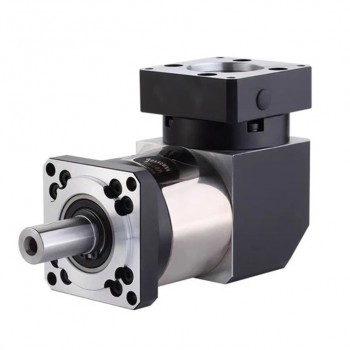
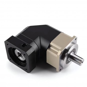
5.Size and Mounting Options:The physical dimensions of the gear motor and its mounting configuration are practical considerations. You must ensure the motor fits within the available space and can be securely mounted. Common mounting styles include flange mounts, face mounts, and foot mounts. The orientation of the output shaft (e.g., in-line, right-angle) is also a key factor in fitting the motor into the machinery’s design.

Efficiency improving methods of helical planetary gearbox

1.Basic knowing about helical planetary gearbox
A helical planetary gearbox combines the compact, high-torque design of a planetary system with the smooth, quiet operation of angled helical teeth, ideal for robotics, automotive, and precision machinery needing high load capacity and low noise, though it creates axial thrust requiring extra bearings and can be more costly than spur gear versions. The angled teeth engage gradually, sharing the load over a larger area, leading to better performance but also generating axial forces.

2.Working principle of helical planetary gearbox
1.Input: Power enters via the input shaft, rotating the central sun gear.
2.Meshing: The sun gear’s rotation forces the planet gears to spin on their own axes and simultaneously orbit the sun gear, as they mesh with both the sun and the internal teeth of the ring gear.
3.Load Sharing: Because multiple planet gears engage at once, the load is distributed, allowing for high torque capacity in a compact space.
4.Helical Advantage: The angled teeth of the helical gears engage more gradually and smoothly than straight (spur) gears, reducing noise, vibration, and stress, while improving power transmission.
5.Output: The planet carrier, which holds the planets, rotates with them. When the carrier is fixed, the ring gear often becomes the output; when the ring gear is fixed, the carrier is the output (or vice versa), providing speed reduction and torque multiplication.

3.Technology advantages of helical planetary gearbox
1.Smooth and Quiet Operation:Helical gearboxes operate smoothly and quietly due to their angled teeth design. This design enables gradual gear engagement, resulting in continuous power transfer. Compared to spur gears, helical gearboxes produce less vibration and noise, making them suitable for low-noise applications.
2.High Load Capacity:Helical gearboxes offer superior load-bearing capacity compared to straight-cut gears. The angled tooth design distributes force across a larger contact area, enabling higher load handling without risking damage or premature wear. This increased capacity allows for the use of smaller gears in power transmission applications, resulting in more compact and lightweight gearbox designs.
3.Evenly Distributed Load:Helical gearboxes distribute loads evenly across gear teeth due to their angled tooth design. This design allows multiple teeth to engage simultaneously, sharing the load and reducing stress on individual teeth. The gradual engagement of helical gear teeth contrasts with the all-at-once engagement of spur gears.
4.Compact Design:Helical gearboxes provide design flexibility. Their small size enables creative and streamlined machine designs, potentially enhancing product aesthetics and functionality. The reduced size can also improve heat dissipation due to less mass retaining heat, potentially increasing gearbox efficiency and longevity.
5.Versatile Configurations:Helical gearboxes offer diverse configurations to meet specific application needs. Shaft orientations include parallel, right-angle, and multi-stage designs, adapting to space constraints and operational requirements.
6.mproved Durability:The gradual tooth engagement in helical gears decreases shock and impact during operation, improving durability. This results in reduced tooth breakage and increased resistance to fatigue, particularly in high-speed or high-load applications. Helical gears’ ability to handle greater torque capacity also contributes to their longevity.
7.Ability to Connect Non-parallel Shafts:Helical gearboxes connect non-parallel shafts, a feature that distinguishes them from other gear systems. This capability enables power transmission between offset or intersecting shafts at various angles, including right angles. Engineers can design more compact and space-efficient machinery layouts using helical gears.

4.Efficiency improving methods of helical planetary gearbox
1.Tooth Surface Modification: Combining helix modification with drum shaping reduces transmission errors by roughly 19.9% and vibration by 21%. This minimizes “edge contact” under load, lowering local friction.
2.Reduced Sliding Contacts: Using “double staggered helical gears” with shortened teeth can improve transmission efficiency by about 1.8 percentile points by avoiding contact in high-sliding zones.
3.Helix Angle Tuning: While larger angles improve smoothness, they generate axial thrust that increases bearing friction. Maintaining the helix angle between 10° and 25° is often optimal for balancing smoothness with power loss.
4.Surface Finish Optimization: High-precision grinding (Grade 6 accuracy) and abrasive flow finishing can increase efficiency by up to 3.3% by minimizing surface roughness and friction.
5.Specialized Coatings: Low-friction coatings (e.g., diamond-like carbon) and case-hardened carburized steel are used to reduce wear and maintain smooth surfaces over the gearbox’s lifespan.
6.Lightweighting: Replacing standard steel housings with high-strength alloys or carbon fiber-reinforced composites can reduce overall weight by 20–30%, lowering inertia-related losses.
7.Bio-based & Synthetic Lubricants: Advanced synthetic and bio-based oils (expected to reach 15% application by late 2025) provide superior temperature stability and lower viscosity-related churning losses.
8.Smart Lubrication Systems: Implementing closed-loop, digitally integrated lubrication can extend drain intervals by 35% and reduce energy intensity by up to 12%.
9.Optimized Immersion: Utilizing SPH modeling to find the ideal oil immersion depth (e.g., ~3.0h) can increase lubricant volume in the meshing zone by 183%, significantly reducing heat and friction.
10.Variable Speed Drives (VSD): Integrating VSDs helps manage input speeds to keep the gearbox within its most efficient load range.

Design problems of right angle planetary gearbox

1.Knowing about the right angle planetary gearbox
A right angle planetary gearbox is a gear drive or speed reducer where the input and output shafts are positioned at a 90-degree angle to each other. It utilizes an epicyclic (planetary) gear arrangement—consisting of a sun gear, planet gears, a planet carrier, and a ring gear—to distribute the load across multiple gear meshes, resulting in high torque density, increased efficiency, and a compact design. The key distinction from a standard in-line planetary gearbox is the inclusion of a bevel or hypoid gear set, which facilitates the change in the axis of rotation.

2.Key components of right angle planetary gearbox
1.Sun Gear: The central driving gear, usually connected to the input motor shaft, that initiates the movement of the system.
2.Planet Gears: Multiple gears (typically three or more) that mesh with the sun gear and orbit around it. Distributing the load among these gears is the reason for the system’s high torque capacity.
3.Ring Gear (Annulus): The outer stationary ring with internal teeth that enclose the entire assembly and mesh with the planet gears.
4.Planet Carrier: A structural component that holds the planet gears in alignment and typically serves as the output shaft, delivering the reduced speed and increased torque.
5.Right-Angle Gearing: An integrated stage of gears (commonly spiral bevel gears for quiet, smooth operation, or hypoid gears for high torque and an axis offset) that intercepts the power flow and changes its direction by 90 degrees.

3.Performance features of right angle planetary gearbox
1.High Torque Density and Capacity: The planetary design distributes the load across multiple planet gears simultaneously, allowing the gearbox to transmit a high amount of torque relative to its compact size. This makes it suitable for heavy-duty applications and high shock loads.
2.High Efficiency: Due to the efficient rolling contact of the gears, these gearboxes typically boast very high mechanical efficiency, often exceeding 95% per stage, which minimizes energy loss, heat generation, and operating costs.
3.Wide Gear Ratio Range: The modular nature of the planetary stages allows for a broad spectrum of reduction ratios, which can be tailored to meet diverse speed and torque requirements (from 3:1 to over 300:1).
4.Low Backlash: Many right angle planetary gearboxes are precision-engineered to offer very low backlash (as low as 2 arc-minutes), which is critical for applications requiring accurate positioning and precise motion control, such as in robotics and CNC machinery.
5.High Torsional Stiffness: The rigid construction, often featuring one-piece planet carriers and robust bearings, provides high torsional stiffness, ensuring minimal play and superior positional accuracy.
6.Smooth and Quiet Operation: The combination of precision-cut gears (often helical or spiral bevel) and balanced load distribution results in smoother operation, reduced vibration, and lower noise levels compared to some other gear types.
7.Compact, Space-Saving Design: The right-angle configuration allows the input motor to be placed parallel to the machine body, drastically reducing the overall footprint and making it ideal for confined installation spaces.
8.Durability and Reliability: Constructed with high-grade materials, such as hardened and ground steel gearing and high-capacity bearings, these gearboxes are built for a long service life, even under demanding operational conditions.
9.Versatile Mounting Options: They typically feature standardized input flanges (e.g., ISO 9409) and various output configurations (shaft, hollow shaft, flange), offering design flexibility and easy integration with different servo or stepper motors and machinery layouts.
10.Maintenance-Free Operation: Many models are lifetime-lubricated with synthetic grease and have high ingress protection ratings (e.g., IP65), reducing maintenance requirements.

4.Design problems of right angle planetary gearbox
1.Reduced Efficiency (Compared to In-line Planetary): While planetary gears are efficient, the addition of the right-angle stage (e.g., spiral bevel gears) introduces an extra mesh point and often more sliding contact than pure rolling, slightly reducing overall efficiency and generating more heat.
2.Heat Buildup in Compact Housing: The primary advantage of a compact design also creates a disadvantage in heat management. The smaller surface area can make it difficult for heat to dissipate effectively, potentially leading to lubricant breakdown or overheating if not adequately addressed through cooling fins, proper lubrication choice, or external cooling.
2.Uneven Load Sharing: In an ideal planetary system, the load is shared equally among all planet gears. However, inevitable manufacturing tolerances and installation errors can lead to uneven load distribution, resulting in some gears carrying more load than intended, which reduces durability and lifespan.
3.Radial and Axial Loads: The right-angle configuration, particularly with bevel gears, generates significant inherent axial (thrust) forces in addition to radial loads. The bearing systems must be robustly designed to handle these combined forces effectively without excessive deflection.
4.Managing Backlash in Multiple Stages: Controlling backlash (the small amount of play between meshing teeth) is a key challenge. Achieving extremely low backlash requires tighter tolerances and more expensive manufacturing processes.
5.Noise and Vibration: Like any gearbox, gear meshing generates noise and vibration. The added complexity and multiple contact points can sometimes lead to higher running noise compared to simpler coaxial planetary gearboxes, a factor that needs addressing in sensitive applications.
6.Orientation Sensitivity: The orientation of a right angle gearbox (horizontal vs. vertical mounting) can affect how the lubricant flows to all necessary components. Proper design must account for different mounting configurations to ensure consistent lubrication of all gear meshes and bearings.
7.Inaccessibility for Maintenance: The compact and integrated nature of the design often makes internal components inaccessible for inspection or repair, meaning that issues can be difficult to diagnose without full disassembly.

The main reasons of spindle motor not turning

1.Knowing about CNC spindle motor
A CNC spindle motor is the high-performance electric motor at the core of a CNC machine that rotates the cutting tool with high speed and torque for precise drilling, cutting, and milling. It converts electrical energy into mechanical motion, providing the power and control needed for accurate machining of materials like wood, metal, and plastics. Key features include its high RPM capabilities (often up to 24,000 RPM), high accuracy, and different cooling methods like air or water.

2.Basic structure of CNC spindle motor
1.Motor: Provides the rotational power. It can be an AC induction or DC brushless motor and directly drives the spindle shaft in integral motor designs.
2.Spindle Shaft: The main rotating shaft that holds the cutting tool. It must be balanced and aligned precisely to prevent vibration.
3.Bearings: Support the spindle shaft, reduce friction, and maintain stability during high-speed rotation. Common types include ceramic ball bearings and hydrostatic bearings.
4.Cooling System: Manages heat generated by the motor and high-speed rotation, which can otherwise affect precision and longevity. This often involves a liquid cooling jacket or a separate fan.
5.Tool Holder: The component at the end of the spindle where the cutting tool is mounted. It must hold the tool securely to prevent vibration and ensure accuracy.
6.Clamping System: A system, often incorporating a drawbar, that applies force to securely clamp and release the tool from the holder.

3.Five types of CNC spindle motor
1.DC Spindle Motors:DC spindle motors, available in brushed or brushless configurations, are commonly used in smaller CNC machines, such as desktop routers, hobbyist setups, or compact milling systems. These motors operate on direct current and are typically controlled by simple electronic systems, making them accessible for smaller-scale operations. Brushless DC motors are preferred for their improved efficiency and reduced maintenance compared to brushed versions, which rely on carbon brushes that wear over time.
2.AC Spindle Motors:AC spindle motors are robust, high-power motors designed for industrial CNC machines. These motors operate on alternating current and are typically paired with a Variable Frequency Drive (VFD) to precisely control speed and torque. AC motors are built to handle demanding workloads and are available in various power ratings, often ranging from 1 kW to over 10 kW, making them suitable for heavy-duty applications.
3.Air-Cooled Spindle Motors:Air-cooled spindle motors use fans or natural air circulation to dissipate heat generated during operation. These spindles are designed to be simpler and more affordable, relying on ambient air to maintain safe operating temperatures. They are commonly used in CNC machines where cost and ease of maintenance are priorities.
4.Water-Cooled Spindle Motors:Water-cooled spindle motors rely on a liquid cooling system, typically using water or a coolant mixture, to maintain optimal operating temperatures. These spindles circulate coolant through a jacket or channels around the motor, dissipating heat more effectively than air-cooled systems. They are designed for long-duration, high-performance tasks.
5.High-Speed Spindle Motors:High-speed spindle motors are engineered to operate at extremely high revolutions per minute (RPM), often exceeding 24,000 RPM and reaching up to 60,000 RPM or more. These spindles are designed for applications requiring fine, detailed work and are typically equipped with precision bearings to minimize vibration and ensure smooth operation.

4.The main reasons of spindle motor not turning
1.Power Supply Issues:This is often the first and most obvious suspect. If the spindle motor isn’t receiving power from the VFD (Variable Frequency Drive) or the main controller, it simply can’t spin. It could be due to a tripped breaker, a blown fuse, or a loose power cable.Power fluctuations or surges can also damage internal components, leading to spindle inactivity.
2.VFD Configuration Errors:The VFD acts as the brain for your spindle motor. If it’s not programmed correctly or if its settings have been changed accidentally, it may fail to send the correct signals to start the motor.This includes issues like incorrect frequency, motor ID mismatch, or locked safety interlocks.
3.Emergency Stop Engaged:You’d be surprised how often the emergency stop button is still activated, cutting off power to the motor. It’s easy to overlook, especially if multiple operators are involved.
4.Wiring or Connector Faults:Damaged, frayed, or loose wiring between the VFD, control panel, and the spindle itself can interrupt signal flow. Similarly, burned connectors or broken terminals may silently block current from reaching the motor.
5.Internal Spindle Motor Failure:If the spindle has been subjected to overheating, moisture ingress, or mechanical damage, internal components like windings or brushes (if applicable) may be damaged beyond function.
6.Software or Controller Glitch:CNC control software can sometimes freeze, miscommunicate, or fail to initialize the spindle due to bugs, corrupt files, or firmware conflicts.
7.Faulty Relay or Contactor:If the relay responsible for energizing the spindle circuit has failed, your motor won’t receive the “go” command. This often happens with age or after power surges.