Posted on Leave a comment

Several step modes of stepping driver

Step Modes

Stepper drivers for sale online come in a variety of step modes, which influence the rotation speed, size, and action of the drive shaft. A complete set of steps does not necessarily imply a full rotation of the drive shaft. In some instances, multiple complete step sequences are required to achieve a quarter of a turn of the drive shaft. The following sections discuss several different step modes and their characteristics.

Wave Step Mode

Wave step mode is found on a number of older stepper driver models. Wave step mode involves passing energy to one phase of the motor at a time. This creates fluctuating torque, which is unstable. It is also considerably less efficient than other step modes, because energy is lost in between energizing each phase. Because of the energy loss, less torque is produced than with other step modes.

Full Step Mode

With a full step mode driver, both phases of the motor are energized simultaneously and continuously. This produces full torque for all phases of the motor at all times. Full step motors are very stable, and one complete turn of the drive shaft is equal to one complete step sequence. For example, if there are 50 steps in the step sequence, 50 steps equals one 360-degree rotation of the drive shaft.

Half Step Mode

Half step mode is an alternating energy circuit. First, one coil phase is energized, swiftly followed by both coil phases being energized. This technique doubles the resolution of the step sequence. It creates varying degrees of torque because the single coil phase energy produces half the torque of the double coil phase energy. High end models decrease the torque differential by increasing the amount of current that passes through the single coil phase. This enables the single coil to increase torque output. Half step mode is very stable and doubles the possible resolution and number of step positions. A 50-step sequence step motor capable of operating in half step mode to allow for greater resolution has 100 step positions.

Micro Step Mode

Micro stepping mode is only available on high end cheap stepper motor drive models, and, as such, are more expensive than other kinds. Micro stepping energizes each coil to a set fraction, allowing fractional steps to occur. This creates very high resolution and precise stepping. Micro stepping creates a very smooth step motion, and some models can move at 1/256th of a step.

Posted on Leave a comment

Four Step for You to Choose A Stepper Motor With Gear

For design engineers in the process of selecting components for an application, the motor or gearmotor can be one of the more difficult components to source. There are so many types of motors and gearmotors all screaming for your attention and promising to be the “most efficient”, the “highest quality” or boasting about “high precision”. Groschopp uses 4 simple steps to lead designers to the best motor/gearmotor choice for a particular application. There are several key design parameters that should be considered when selecting a motor or gearmotor for a motion control application.

Table 1: Gear stepper motor Selection Process – steps to complete to ensure a gearmotor properly matches the application

As the motor or stepper motor planetary gearbox selection process begins, the designer must gather the relevant technical and commercial requirements. This first step is often overlooked, but it is a critical component in the design process. The gathered design inputs information will then be used in the selection process and will dictate the ideal motor for the application. Failure to gather the proper inputs can lead the designer down an untended path. For this reason, it is helpful to use the Application Checklist (Table 2) when developing the motor specification. These parameters, along with some project specific requirements, will be helpful when navigating the selection process.

Table 2: Application Checklist – use this checklist to help formulate the specific requirements to ensure the gearmotor vendor has the critical information necessary to achieve the best match between the gearmotor and the application

Next, the designer must consider what type of motor technology best suits the intended application. Using the design inputs, the Motors Quick Reference Guide (Table 3) can be used as a selection matrix in the first step of the decision process. This reference guide details four common motor types and provides general information to consider when selecting each stepper motor spur gear. Because each application has its own unique characteristics, it is important to determine which of the parameters (e.g. horsepower, efficiency, life, starting torque or noise ratings) are most important to the application under consideration. During the motor selection process, by looking at the required speed and torque of the application, it should become evident to the designer if the motor chosen requires a gearbox to meet the necessary requirements. If a gearmotor is necessary for the application, another level of complexity will be added and several additional criteria need to be evaluated.

Posted on Leave a comment

Why Do We Microstep a Stepping Motor?

Microstepping can improve stepper motor system performance in a number of applications, and it can reduce system cost and complexity relative to half- and full-step driving techniques. In addition, microstepping can help solve noise and resonance problems all while increasing step accuracy and resolution.

A stepper motor system’s natural frequency is determined by holding torque, rotor and load inertia, and the number of full-steps per revolution. When stepper motor system damping is low you risk generating noise or losing steps when the stepper motor operates at or near the resonant frequency depending on damping, total inertia, and the type of stepper motor. These issues can happen at or near integer multiples and fractions of the natural frequency. Typically the frequencies closest to the natural frequency cause the most problems.

The principal source of these resonances is that the stator flux moves in a discontinuous way when you use a non-microstepping stepper motor driver — forty-five or ninety degrees at a time — causing a pulsing energy flow to the rotor, and these pulsations excite the resonance. Using half-steps rather than full-steps reduces the excitation energy to roughly twenty-nine percent of the full-step energy. If we microstep the motor in 1/32-full-step mode only point one percent of the full-step energy remains. You can reduce the excitation energy to a low enough level that all resonances are completely eliminated by microstepping.

However, this is only true of an ideal stepper motor. In practical applications there are additional sources that excite system resonances. Regardless, microstepping improves movement in nearly all applications and, in many cases, microstepping alone will sufficiently reduce noise and vibrations for most applications.

When you run a stepper motor at low frequencies in half- or full-step mode the movement is discontinuous, noise and vibrations are generated, and there will be significant ringing. The frequencies where this occurs are below the stepper motor system’s natural frequency, which is why microstepping offers a safe, simple means of extending noiseless stepping frequencies approaching zero hertz.

You don’t usually need steps smaller than 1/32-full-step — electrical step angles this small are easily absorbed by the stepper motor’s internal friction, meaning the stepping doesn’t generate overshot or ringing. The microstepping positions will deviate from a straight line because of uncompensated sine/cosine profiles.

Posted on Leave a comment

How to Protect Stepping Motor from Resonance Issues

Step motors are unique among electronic motors in that they move in a series of discrete steps (hence their name) rather than a continuous motion. This is a useful property since it allows steppers to have positional and velocity control that is both accurate and easy and doesn’t even require feedback to maintain (under normal operation). However, one of the primary disadvantages of this style of motor comes as a direct result of this discrete nature and open loop control.

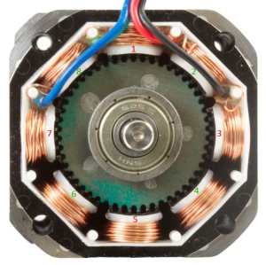
Cross-Section of a Hybrid Bipolar Stepper

When a stepper takes a single step, it will overshoot its target destination slightly and will oscillate a bit before settling down on target. This is due mostly to the inertia of the rotating mass briefly overpowering the magnetic field of the motor. This isn’t a big deal by itself but when you start chaining multiple steps together to get a larger movement this oscillation occurs at each step taken on the way. If the frequency that the controller is outputting new step commands to the motor matches the natural frequency of the motor then the oscillations will tend to become more severe as they propagate through the motor. Eventually they are so large that they will overpower the magnetic field for long enough on a given step to miss the subsequent step command, and you begin missing steps. Since steppers are typically run in open loop, the controller has no knowledge of these missed steps; The result is the motor will not get to its destination successfully. The effect can become so pronounced that the motor loses torque completely and stops rotating. Depending on the synchronization of the steps, it can even reverse the direction of rotation.

Why are steppers still so popular then? As bad as this issue sounds, there are a few mitigating factors. First, this phenomenon is only problematic at the stepper’s natural frequency. This means that it will only be at work in a certain velocity band. Depending on what speeds you are running your motor at, you may never even notice it at all! Second, the resonance takes time to build up. It’s not like you will hit a bad velocity and immediately lose torque. The oscillations will take a few seconds to get to the troublesome levels. Since this issue only crops up at certain velocities, you can typically accelerate through a bad region and emerge unaffected on the other side. You are only at risk if you are staying in the bad region for extended periods of time. Finally, this effect is greatly reduced by having load on the motor. If the motor has load on it, then the inertia is much greater and the oscillations will be reduced substantially. Notice how in the video, when I apply some pressure with my hand (effectively loading the motor down) it starts operating normally again. You are far less likely to experience ringing on a motor that is loaded than on one that is not. This is good since the vast majority of the time the motor will be loaded (what are you using it for after all?).

There are commercially available dampers, like the MDR Damper Roll and  Nema17 Dampers, that act sort of like a flywheel that can be attached to the rear shaft of a stepper to artificially load it down to combat ringing, if necessary (though I cannot speak to their effectiveness).

Overall, provided you know about the problem it is fairly easy to avoid. The best thing to do when you get a new stepper is to quickly run it through the available velocity range and find where the motor has trouble keeping torque. That is the region you should avoid in your application.

Posted on Leave a comment

How to control such kinds of stepping motor easily

Today we will talk about how to control such a motor together with a simple example, involving a H-bridge electronic circuit and simple scripting. In our implementation we have used a nema 23 bipolar stepper motor, however minor changes in control sequences are required for other types of stepper motors.

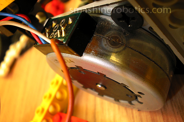
Stepper Motor attached to LEGO build

To summarize, the electromagnetic coils are located on the stator of the stepper motor, while permanent magnets, equal in pair numbers, are located on the rotor. A more detailed discussion about stepper motors can be found in our dedicated article, but making a long story short, like any DC motor, these motors rotate when the coils are energized however, if the coils are continuously energized in the same way, the movement will stop when opposite magnetic poles are aligned, e.g. S-pole on coil aligned with N-pole on rotor permanent magnet.

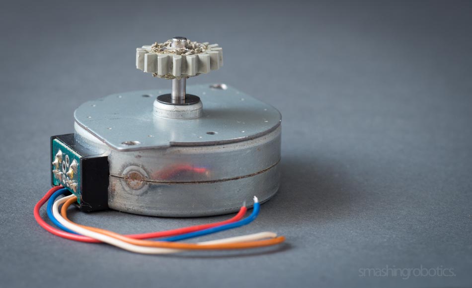
Bipolar stepper motor with attached LEGO 16 tooth gear

Electromagnetic coils found in a bipolar hybrid stepper motor  are arranged as independent windings, each of them corresponding to one phase. Usually such stepper motors have 6 terminals, 5 if the common wires of the two windings are internally connected, and the terminals can be identified by measuring the resistance between terminals using a multimeter.

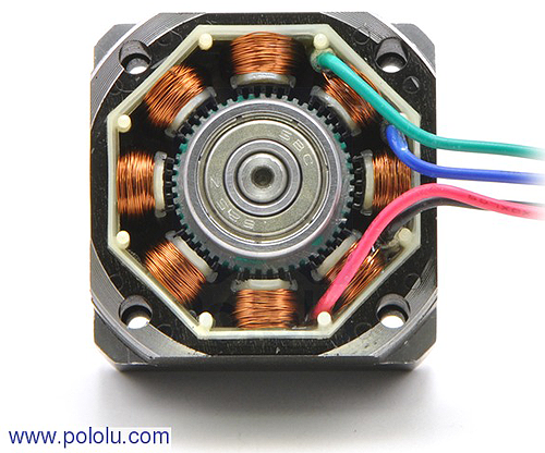
Stepper motor

In short, if resistance of a coil, between its two end terminal has a certain value, the resistance between the common lead and any of its terminals must a value divided by 2. In 5-lead motors, coil terminals can be determined by touching each two wires together. When the rotor shaft becomes harder to turn it means that the two connected wires belong to the same winding.

Posted on Leave a comment

Something about stepper driver you may not know

If one is trying to select the driver for the stepper motor that one is using then it is wise that they know certain facts regarding it. As one reads through they will understand certain facts which need to be known regarding these drivers.

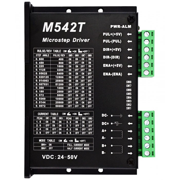
Nema 23 Stepper Motor Drive 24-50VDC 1.5A-4.5A 256 Microstep M542T

What is a Stepper Motor Driver?

Before one settle to have one driver it is wise to know what actually such drivers are.

1. A step motor driver is an electronic device which is used for running the stepper motor.

2. It does not actually do anything on its own, but it needs to be used with a controller.

3. There are various natures of such drivers that need to be selected according to the motor that one has.

4. The basic function of them is to drive the motor that is in use.

The Necessity of Such Driver

It is good to know why actually require such driver stepper motor.

1. The voltage and the current required by such motor cannot be produced by the controller.

2. For this very reason, a driver is required.

3. This electronic device will transform the movement instruction from a controller into a sequence.

4. This will be fed into the winding that is there in unipolarstep motor so that it is turned on or off and at the same time make available the required power for its movement.

5. Such an effect can be had by using microcontroller, but that is time consuming due to the design and programming required.

6. Instead, if such drivers are used, it can be done instantaneously.

The Various Types of Drivers Available

There are certain types of drivers available. It is better to know about those so that the best can be selected for use. There are basically two types of drivers. Namely, they are constant voltage drivers and constant current drivers.

Constant Voltage drivers

1. This variety of drivers are less costly than the constant current drivers

2. Such drivers use voltage to create torque

3. It can be said that usually, such drivers are not so efficient

4. The performance of these drivers is worse than the constant current drivers.

Constant Current drivers

1. This nature of the driver is costlier than the constant voltage driver.

2. The circuits used in these drivers are more complex than that used in the other variety.

3. There is a use of a constant flow of current for producing the torque required.

4. The performance of these drivers is better than the constant voltage driver.

It is generally seen that the constant current drivers are commonly used as the performance that can be achieved is better. Another reason for its popularity is the availability of many ICs.

Features of Certain Drivers

It is good to know about the features of certain types of drivers.

Digital Stepper Driver

These drivers are implemented using the most modern technology available. It can be said that such drivers are easy to use and they can be effectively used for driving 2-phase or 4-phase motors. Its working does not produce heat and noise. It is also seen that it can work with a current of 18-30v DC and the maximum current that can be produced is 2.2 A. The DIP switch need to be set so that the required current and micro-steps required can be achieved.

1. One can expect to have anti-resonance for having optimal torque.

2. The motion is smooth with no production of heat and noise.

3. One can expect to have step and direction control when using these drivers.

4. It offers multi-stepping for producing smooth movement of the motor.

5. One can expect to have 8 micro-steps which can be selected as required.

6. When such a driver is used then one can expect to have protection from over-current and voltage.

Analog Stepper Driver

Such driver is built using THB7128 IC by reputed manufacturers. One when using such a driver can expect to have micro-step resolution as much as 25600 steps per rev.

If one looks at the key features of this nature of drivers then it can be noticed that they are as follows.

1. The driving voltage is 10-32VDC

2. There are 8 current options with Maximum of 3A.

3. Micro-step resolution that can be achieved is from 1 to 128 with 8 options.

4. One can expect to have H-bridge Bipolar steady current drive.

5. The signal input and output are optically isolated.

6. The single pulse interface uses standard common anode.

7. When one uses such a driver in the motor then it can be ensured that off-line protection is achieved.

8. The housing is semi-closed housing so it can efficiently adapt to the rough working condition.

9. Automatic semi-flow lock function is also another feature of this driver.

So, one need to select the driver, according to requirement and it must be had from reputed manufacturers.

Posted on Leave a comment

How to Use a Step Motor in Different industries

There are motors everywhere in the world around us– in cars, printers, computers, washing machines, electric razors, you name it. Unfortunately, there are a lot of people (myself included up until very recently) that wouldn’t know what to do if they were handed a motor and told to run it. So I decided that I want to change that. Let’s learn to run a stepper motor!

Stepper motors are one of the three main classes of motors: the other two are DC motors and servo motors. As a brushless motor, the central shaft of a stepper motor does not physically touch anything in order to rotate. Rather, stepper motors use electromagnets that are concentrically located around the central shaft to induce it to rotate.

But how do you actually control and run a stepper motor? There are two modes that can be used to operate a stepper motor: unipolar and bipolar mode. Unipolar mode only operates in the positive voltage range. Normally, this would mean that current could only be driven in one direction through the electromagnetic coils, producing a magnetic field in only one direction, implying that the central shaft would only be able to tilt back and forth between the two electromagnets.

When current can only flow in one direction through a coil, the shaft is unable to rotate the full 360 degrees.
Bipolar hybrid stepper motors also have current flow in two different directions through the coils. Instead of using a central tap, they use both positive and negative (bipolar) voltage to induce the current flow in both ways through the coil. Because current is able to flow through the entire coil, instead of just half of the coil in unipolar mode, bipolar stepper motors have more torque to rotate and hold the central shaft in place.

Posted on Leave a comment

Resolution and positioning accuracy of stepping motor

The resolution and positioning accuracy of a stepper motor system is affected by several factors-the stepper angle (the stepper motor full-step length), the selected drive mode (full-step, half-step or microstepping), and the gear rate. This means that there are several different combinations which can be used to get the desired resolution. Because of this, the resolution problem of a stepper design can normally be dealt with after the motor size and drive type have been established.

NORMAL SELECTION STEPS
1. Determining the drive mechanism component

Determine the mechanism and required specifications. First, determine certain features of the design, such as mechanism, rough dimensions, distances moved, and positioning period.

2. Calculate the required resolution

Find the resolution the motor requires. From the required resolution, determine whether a motor only or a geared motor is to be used. However, by using the microstepping technology, meeting the required resolution becomes very easy.

3. Determine the operating pattern

Determine the operating pattern that fulfills the required specifications. Find the acceleration (deceleration) period and operating pulse speed in order to calculate the acceleration torque.

4. Calculate the required torque

Calculate the load torque and acceleration torque and find the required torque demanded by the motor.

5. Select the motor

Make a provisional selection of a motor based on the required torque. Determine the motor to be used from the speed-torque characteristics.

6. Check the selected motor

Confirm the acceleration/deceleration rate and inertia ratio.

MOTION CONTROL PRODUCTS’ STEPPER MOTORS
Motion Control Products offer many series stepper motors, such as 2-phase stepper motors and 3-phase stepper motors (from NEMA frame size 8 to NEMA frame size 42) are available. Our stepper motors adopt advanced technology from U.S.A, using high-class cold roll sheet copper and anti-high temperature permanent magnet. Motion Control’s stepper motors are distinguished for their high reliability and low heating. Due to their internal damping characteristics, our stepper motors can run very smoothly and have no obvious oscillating area within the whole speed range of the motors. The PDF overview (downloadable below) shows the typical models of Motion Control Products stepper motors.

Posted on Leave a comment

Open-loop Position Control with a Stepper Motor

With the increasing popularity of DIY projects such as quadcopters, CNC tables and 3D printers, many people are faced with the decision of which type of motor to use in their project. For applications that require precise control of the position of the motor, the common choices are DC motors with encoders, servo motors, and stepper motors.

First, let’s take a look at what the control system looks like on a stepping motor for sale without an encoder. Suppose you want the stepper to make one complete rotation. Your program knows your motor’s step angle is (for example) 1.8°, so it tells your controller to move 200 steps clockwise. The controller tells this to the driver chip, and the driver chip outputs the power signals that turn the motor. Next, suppose you want the motor to turn half a rotation counter-clockwise from it’s original starting location. Your program remembers the motor is 200 steps away from the starting position, so it tells the controller to move 300 steps counter-clockwise, and so on.

openloop

This is known as open-loop control. You have precise control over the position of the motor, but only under the assumption that the motor has physically done exactly what it’s been told to do. If the motor takes an extra step due to excessive inertia, if the motor stalls, or if you’re using a gearbox stepper motor that has significant backlash, your program’s assumption of the motor’s current state will be wrong.

Closed-loop Position Control with a DC Motor and Encoder


Posted on Leave a comment

Difference Between Four, Six and Eight Wires Steping Motor

I have a stepper motor with either 4, 6, or 8 lead wires available to connect to a stepper drive. What is the difference between these wiring types, and does this affect how I connect the motor to my drive?

Solution
The basic operation of any stepper motor online relies on the use of inductive coils which push or pulls the rotor through its rotation when they are energized. A pair of wire leads coming from a stepper motor will correspond to at least one of these windings and possibly more depending on the motor type. In each of the following cases a chassis ground lead is also pictured to ensure the motor is correctly grounded.

4-Wire Stepper Motors
While many motors take advantage of 6- and 8-wire configurations, the majority of bipolar (one winding per phase) stepper motors provide four wires to connect to the motor windings. A basic 4-wire stepper motor is shown in Figure 1. Connecting this motor type is very straightforward and simply requires connecting the A and A’ leads to the corresponding phase outputs on your motor drive.


6-Wire Stepper Motors
A 6-wire stepper motor is similar to a 4-wire configuration with the added feature of a common tap placed between either end of each phase as shown in Figure 2. Stepper motors with these center taps are often referred to as unipolar motors. This wiring configuration is best suited for applications requiring high torque at relatively low speeds. Most National Instruments stepper motor interfaces do not support 6-Wire stepper motors, although some motors do not require the center taps to be used and can be connected normally as a 4-wire motor.


8-Wire Stepper Motors
Some nema 23 motors are also offered in 8-Wire configurations allowing for multiple wiring configurations depending on whether the motor’s speed or torque is more important. An 8-wire stepper motor can be connected with the windings in either series or parallel. Figure 3 shows an 8-Wire stepper motor with both windings of each phase connected in series. This configuration is very similar to the 6-wire configuration and similarly offers the most torque per amp at the expense of high speed performance.

It is also possible to connect an 8-wire stepper motor with the windings of each phase connected in parallel as shown in Figure 4. This configuration will enable better high speed operation while requiring more current to produce the rated torque. This connection type is sometimes known as parallel bipolar wiring.

Although every stepper motor operates in the same basic way, it is important to understand the difference between each wiring type and when each should be used.