Installation precautions of right angle planetary gearbox

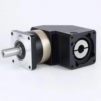
1.Basic concepts of right angle planetary gearbox
A right angle planetary gearbox is a precision mechanical transmission device that combines the high torque, compact design, and low backlash of a planetary gear system with a bevel gear stage to redirect rotational motion by 90° between the input and output shafts. Unlike inline planetary gearboxes (coaxial input/output), this design enables space-efficient power transmission in applications where axial mounting is impossible—making it a critical component in CNC machinery, industrial robotics, automation, and motion control systems.

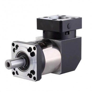
2.Key components of right angle planetary gearbox
1.Sun Gear: The central gear, connected to the input shaft (often via a bevel gear), that drives the entire system.
2.Planet Gears & Carrier: Multiple gears that mesh with the sun gear and rotate around it. They are mounted on a planet carrier, which serves as the output shaft, providing high torque.
3.Ring Gear (Annulus): The outer, fixed internal gear that meshes with the planet gears.
4.Right-Angle Input Stage (Bevel Gears): A pinion and gear set that changes the input shaft direction by 90 degrees before entering the planetary set.
5.Housing: Encloses the assembly, provides structural support, and holds the internal components, often featuring specialized output flanges.
6.Bearings: High-capacity bearings (e.g., cross-roller bearings) support the high radial and axial loads on the output shaft.

3.The importance of right angle planetary gearbox
1.Space-Saving and Compact Structural Design:The most prominent advantage of right angle planetary gearboxes is their ability to change the power transmission direction by 90° while maintaining a compact volume, which solves the layout dilemma of mechanical equipment with limited installation space.
2.High Transmission Efficiency and Energy Saving:Compared with other right-angle transmission solutions, right angle planetary gearboxes have a significantly higher transmission efficiency, which is critical for energy saving and reducing operating costs of equipment, especially for electric-driven and continuous working systems.
3.High Load-Bearing Capacity and Strong Shock Resistance:Combining the load distribution characteristics of planetary gears and the high load capacity of bevel gears, right angle planetary gearboxes can bear large radial, axial and overturning loads at the same time, and have strong resistance to impact and vibration, which is essential for heavy-duty and harsh working conditions.
4.High Transmission Precision and Low Backlash:For precision control equipment, low backlash and high transmission precision are core performance requirements, and right angle planetary gearboxes are far superior to traditional right-angle transmission components in this regard.
5.Wide Adaptability and Customizable Performance:Right angle planetary gearboxes have flexible structural design and diversified performance parameters, which can be customized according to the different requirements of various application scenarios, and adapt to the working conditions of different speeds, torques, installation methods and environmental factors.
6.Long Service Life and Low Maintenance Costs:The structural design and material selection of right angle planetary gearboxes focus on durability and reliability, which can significantly reduce the maintenance frequency and replacement costs of equipment, and improve the overall uptime of the mechanical system.
7.Perfect Matching with Servo Systems:In the era of industrial automation, servo motors are the core power source of precision control systems, and right angle planetary gearboxes are the optimal transmission matching component for servo motors due to their structural and performance characteristics.

4.Installation precautions of right angle planetary gearbox
1.Pre-Installation Preparation Principle:Pre-installation preparation is the foundation of standard installation, and the core principle is to eliminate hidden dangers such as unqualified parts, mismatched dimensions and contaminated components before assembly.
2.Centering and Alignment Principle:The most critical principle for the installation of right angle planetary gearboxes is strict centering and alignment between the gearbox and the connected equipment, which is to avoid additional radial load, axial load and overturning moment caused by misalignment.
3.Fastening Principle:Fastening of fasteners follows the principle of uniform force, specified torque and multi-stage anti-loosening to prevent fastener loosening caused by vibration during operation, which leads to coaxiality deviation, oil leakage and even structural disconnection.
4.Sealing Protection Principle:The right angle planetary gearbox has multiple sealing points, and the installation principle of sealing protection is to ensure the integrity of the sealing structure and the tight fit of the sealing surface to avoid lubricating oil leakage and foreign matter entering the inner cavity.
5.Load and Mounting Orientation Principle:Right angle planetary gearboxes have strict requirements for load direction and mounting orientation, and the core principle is to operate within the rated load range and comply with the product’s mounting orientation restrictions to avoid structural damage caused by overload or unreasonable force.
6.Commissioning and Trial Operation Principle:After the mechanical installation is completed, the commissioning and trial operation must follow the principle of no-load first, then load; low speed first, then rated speed to verify the installation quality, and shut down immediately to check when abnormalities are found, to avoid expanding the fault range.
7.Post-Installation Fixation and Marking Principle:The post-installation work follows the principle of reinforcing the protection of vulnerable parts and making complete installation records to facilitate subsequent daily maintenance, fault troubleshooting and regular inspection.

How to reduce the noise of CNC spindle motor?

1.Basic knowing about CNC spindle motor
A CNC spindle motor is a high-precision, high-performance electric motor that serves as the core power and rotation component of a CNC machine tool. It drives the cutting tool to rotate at a controllable speed, providing the necessary torque and rotational speed for material cutting, milling, drilling, grinding and other machining operations. Its rotation parameters are precisely regulated by the CNC system to match different machining processes, materials and tool requirements, ensuring the accuracy, efficiency and consistency of CNC machining.

2.Main structure of CNC spindle motor
1.Stator and rotor: Like most electric motors, spindle motors have a stator and rotor. The stator is the stationary part of the motor, while the rotor rotates around the stator.
2.Bearings: Spindle motors typically use high-precision bearings to ensure smooth rotation and accuracy.
3.Enclosure: The motor is often enclosed in a protective housing to prevent damage from debris or other environmental factors.
4.Cooling system: Spindle motors generate a significant amount of heat during operation, so a cooling system is typically required to keep the motor within safe operating temperatures.
5.Drive mechanism: The motor is typically connected to the spindle via a drive mechanism, such as a belt or gear system.

3.Main advantages of CNC spindle motor
1.Shorten non-cutting time: Rapid start-stop and seamless speed switching eliminate the waiting time of speed adjustment/start-stop in traditional machining; matching with high-speed tool change of CNC machining centers, the non-cutting time of a single workpiece can be reduced by 30%~50%.
2.Improve cutting efficiency: High low-speed torque realizes heavy-duty rough cutting, and constant high-speed power ensures efficient finish machining; the processing time of a single workpiece is shortened by 20%~40%, and the daily output of the workshop is significantly improved.
3.Eliminate machining errors caused by motor factors: Ultra-low rotational runout and high speed stability avoid tool eccentricity, speed drop and other problems, ensuring the dimensional accuracy and surface finish of workpieces.
4.Stable precision for batch production: The motor has no obvious performance attenuation during long-term operation, and the machining precision of the first and the 1000th workpiece in batch production is basically consistent; the defective rate of precision parts is reduced by 60%~80%, and the product qualification rate is greatly improved.
5.Meet high-precision machining demands: Direct-drive models can realize micron-level machining precision, meeting the processing requirements of high-end industries such as aerospace, automotive core parts and precision molds.
6.Switchable control modes: Speed/torque/position three control modes can be switched freely through the CNC system, realizing multi-process continuous machining of a single workpiece without replacing the power unit.
7.Compatible with various cutting tools: Match with mainstream tool clamping systems, suitable for drill bits, milling cutters, lathe tools, engraving tools and other cutting tools of different specifications, meeting the processing demands of multi-variety small and medium batch production.

4.Common methods of reducing noise of CNC spindle motor
1.Inspect and replace bearings promptly:If you hear bearing noise, check immediately. Turn off the machine, disconnect the power, and manually rotate the spindle. Feel for friction or resistance.If the noise persists, replace the bearing with the correct specification.
2.Tighten and rebalance the cutting tools:Check that the chuck and cutting tools fit correctly. Replace any worn or deformed parts. Always clean the tool holder and tool post before installation to ensure a tight fit and prevent vibration.For frequent high-speed operation, use precision-balanced cutting tools to minimize the risk of vibration-induced noise.
3.Check for electrical abnormalities:Use a multimeter or spindle diagnostic software to check for voltage drops or frequency inconsistencies. Ensure the frequency converter (VFD) settings are perfectly matched to the spindle specifications. Eliminate any wiring or grounding issues to prevent electrical noise from escalating into a larger problem.
4.Clean the internal parts of the motor:If you suspect spindle contamination, disassemble the spindle for internal cleaning. Clean the surface with compressed air, a lint-free cloth, and a suitable degreaser. Inspect the seals and filters, and replace them if damaged. Keep the work area clean to prevent dust from entering.
5.Rebalance or replace the spindle:If a spindle bend is suspected, perform a runout test using a dial indicator. Any noticeable deviation indicates spindle misalignment or damage. Depending on the severity, the spindle may need to be rebuilt or replaced.
6.Maintain the cooling system:Inspect the fan blades for damage and remove any debris. Replace the faulty fan or upgrade to a quieter, more efficient one. For water-cooled systems, flush the coolant circuit to remove air bubbles and check the water pump’s performance. Excessive pump noise may indicate impeller failure or inlet blockage.

What are the design difficulties of linear stepper motor?

1.Concepts of linear stepper motor
A linear stepper motor is a high-precision electromechanical actuator that directly converts electrical pulse signals into fixed incremental linear motion, rather than rotational motion like traditional rotary stepper motors. It eliminates the need for intermediate mechanical transmission components (e.g., ball screws, gear racks) to realize linear displacement, making it ideal for applications requiring accurate positioning and rapid response.

2.Core mechanical elements of linear stepper motor
1.Stator: A stationary outer ring housing electromagnetic coils (windings). When energized in sequence, these coils generate magnetic fields that drive the motor’s internal motion.
2.Rotor: The rotating internal part, typically containing permanent magnets and toothed silicon steel laminations. In a linear stepper, the rotor often functions as a precision nut.
3.Lead Screw: A threaded rod that replaces the standard motor shaft. As the rotor-nut rotates, it drives the lead screw forward or backward along a straight path.
4.Anti-Rotation Mechanism: Essential for converting rotational force into linear travel. Depending on the motor type, this is either built into the housing (captive) or required as an external guide (non-captive).
5.Bearings: High-quality ball bearings support the rotor to ensure smooth, low-friction operation and extend the motor’s lifespan.

3.Performance advantages of linear stepper motor
1.Step-wise Displacement Control: Each electrical pulse corresponds to a fixed linear step pitch (usually μm-level resolution). The position is directly determined by the number of pulses, realizing open-loop precise positioning without additional position sensors (e.g., encoders) for most low-load scenarios.
2.Excellent Repeatability: The repeat positioning accuracy can reach ±1~±5 μm. There is no transmission backlash caused by mechanical components (such as ball screw gaps), which is especially suitable for high-precision reciprocating motion scenarios (e.g., semiconductor wafer handling, 3D printer Z-axis drives).
3.No Intermediate Transmission Components: It directly converts electrical pulses into linear motion, eliminating the need for ball screws, gear racks, couplings and other transmission mechanisms. This avoids transmission errors, wear and noise caused by mechanical components.
4.Quick Start/Stop & Reversal: The mover has a small mass and low inertia. It can complete start, stop and reverse actions in a short time, and is suitable for short-stroke, high-frequency reciprocating motion (e.g., SMT pick-and-place machines, precision dispensing pumps).
5.Static Holding Force Without Power Supply: When the motor is powered off, the stator winding still has residual magnetism, which can provide a certain static holding force to prevent the mover from slipping under load. This is suitable for scenarios requiring position locking (e.g., precision positioning stages).
6.Open-loop Control Capability: The traditional open-loop control mode does not need complex feedback circuits, and the control system is composed of a stepper motor driver and a controller (PLC/microcontroller), which has low hardware cost and easy programming.
7.Energy Consumption Matching Load: The motor only consumes power when moving, and the static holding state consumes low power. Compared with hydraulic/pneumatic linear actuators, it saves more energy and is more environmentally friendly.

4.Design difficulties of linear stepper motor
1.Dimensional Accuracy: Operating temperatures can rise by over 135°F (57°C), causing materials like plastic threads in the rotor to expand significantly more than metal journals (up to .004″ vs .001″). If not precisely managed, this expansion can cause the rotor to rub against the stator wall.
2.Component Degradation: High heat can degrade wire insulation and weaken internal magnets, directly reducing motor torque and efficiency.
3.Critical Frequencies: Resonance occurs if the stepping frequency matches the motors natural frequency (typically around 100–200 pulses per second), leading to audible noise, lost steps, or even total stalling.
4.Damping Complexity: Designers must implement mechanical dampers or complex algorithms (like S-curve profiles) to “smooth out” these vibrations, though higher-order algorithms can introduce their own numerical precision issues and computational burdens.
5.Backlash and Wear: Over time, the axial movement between the screw and nut (backlash) increases due to wear. Designers must often use specialized clearance nuts or anti-backlash designs that sacrifice some efficiency for long-term precision.
6.End Fixity and Buckling: Long lead screws are sensitive to “column loading,” where the screw may buckle under compression if the length is not perfectly balanced with its diameter and speed.
7.Concentricity Issues: Achieving perfect alignment (concentricity) between the internal nut and the lead screw is vital; even minor misalignment can cause severe radial impact forces that destroy bearings or lead screws.
8.Miniaturization Limits: As motors shrink (e.g., micro-steppers for medical use), the magnetic flux density becomes too small to generate usable torque, posing a hard physical limit on how small these devices can realistically be.
9.Electromagnetic Interference (EMI):Operating at the high frequencies required for microstepping can generate significant EMI, which can interfere with nearby sensitive electronics, such as those found in medical or aerospace sensors.

What are the challenges in the design of high-power switching power supplies?

1.Basic concept of switching power supply
A switching power supply is a type of electronic power conversion device that converts electrical energy from one voltage/current form to another required form by controlling the on-off state of semiconductor switching devices (such as MOSFETs, IGBTs, transistors). It is mainly used to provide stable and adjustable DC voltage for electronic equipment, and can realize mutual conversion between AC and DC, as well as step-up, step-down, or inversion of voltage.

2.Working principles of switching power supply
1.Input Rectification & Filtering:Incoming AC (like from a wall socket) is first converted to pulsating DC by a rectifier (diodes).An input capacitor smooths this pulsating DC into a relatively stable, higher DC voltage.
2.Switching/Inverter Stage:This is the core: a power switch (MOSFET) rapidly chops the DC into high-frequency square waves (pulse trains).This high-frequency switching allows for much smaller transformers and inductors, saving space and weight.
3.Energy Transfer (Transformer):The high-frequency pulses are fed to a small transformer, which efficiently steps the voltage up or down (depending on design) and provides electrical isolation.
4.Output Rectification & Filtering:The high-frequency AC from the transformer’s secondary side is again rectified and filtered (with capacitors and inductors) to produce the final smooth, stable DC output for the load.
5.Feedback Control:A control circuit continuously monitors the output voltage.It adjusts the ‘on/off’ time (duty cycle) of the power switch (using Pulse Width Modulation or PWM) to keep the output voltage precisely at the desired level, compensating for input voltage or load changes.

3.Usage advantages of switching power supply
1.High Efficiency:One of the most significant benefits of switching power supplies is their high efficiency, often exceeding 90%. This efficiency arises from the minimal energy loss during the switching process, making them an optimal choice for power-sensitive applications. High efficiency translates to lower energy costs and less heat generation, which can prolong the life of electronic components.
2.Compact Size and Lightweight:Switching power supplies are typically smaller and lighter than their linear counterparts. The use of high-frequency transformers allows for smaller magnetic components, reducing the overall size and weight of the power supply. This compactness is particularly advantageous in portable electronics, where space and weight constraints are critical.
3.Enhanced Reliability:The robust design of switching power supplies contributes to their enhanced reliability. They are less susceptible to overheating and thermal stress, which can lead to component failure. Additionally, many switching supplies incorporate features like over-voltage and over-current protection, further increasing their reliability in demanding environments.
4.Improved Heat Dissipation:Due to their high efficiency, switching power supplies generate significantly less heat than linear power supplies. This reduced heat generation simplifies thermal management and can even eliminate the need for bulky heat sinks or active cooling systems in many applications. Consequently, this leads to more compact designs and improved overall system performance.
5.Cost-Effectiveness:While the initial cost of switching power supplies may be higher than that of linear power supplies, their long-term cost-effectiveness is undeniable. The efficiency gains result in lower operational costs, and the durability of these units can reduce maintenance and replacement expenses. Over time, the benefits of energy savings and reliability can far outweigh the initial investment.

4.The challenges in the design of high-power switching power supply
1.Meeting strict EMC standards (e.g., IEC 61000-3-2 for harmonic emissions, IEC 61000-4 for immunity): High-power systems produce stronger harmonics, requiring larger and more complex EMI filters, which conflicts with miniaturization goals.
2.Reducing parasitic parameters: In high-power circuits, long busbars and large-area copper traces introduce stray inductance, which can cause voltage spikes during switching and damage power devices. Layout optimization (e.g., planar busbars, integrated power modules) is critical but technically demanding.
3.Core saturation: High-power operation requires large magnetic flux, which can easily saturate the core material, leading to a sharp increase in inductance loss and even device burnout. Selecting high-saturation-flux-density materials is necessary, but these materials are expensive and have strict processing requirements.
4.Winding loss and thermal design: High-current windings require thick copper wires or copper foils, but skin effect and proximity effect at high frequencies increase winding loss. Optimizing winding structure is required to reduce loss, but this increases manufacturing complexity.
5.Trade-off between device parameters: High-power devices require low on-resistance (to reduce conduction loss) and fast switching speed (to reduce switching loss), but these two parameters are often contradictory. For example, IGBTs have low conduction loss but slow switching speed, making them unsuitable for high-frequency applications.
6.Voltage and current stress: During switching, power devices bear high voltage spikes and current surges, which can cause device breakdown. Adding snubber circuits to suppress voltage spikes is necessary, but this increases circuit complexity and power loss.
7.Protection function coordination: High-power SPS have multiple protection functions (overvoltage, overcurrent, short-circuit, over-temperature). Coordinating the response speed and action sequence of these protections is critical to avoid misoperation and ensure system safety.