Main typs and protection methods of linear stepper motor

1.Basic learning of linear stepper motor
A linear stepper motor converts electrical pulses into linear motion by using a threaded screw and a nut, where the motor’s rotational movement is converted into a straight, precise movement. The motor’s rotor turns, causing either the screw or the nut to move linearly along the other, depending on which part is fixed. Key features include precise positioning, high repeatability, and a smooth, controlled movement, making it ideal for applications like robotics and automated machinery.

2.Working principles of linear stepper motor
1.Coil Energization:When current flows through a coil, it generates a magnetic field. Depending on the polarity of the current, one side of the coil becomes a north pole and the other a south pole.
2.Magnetic Alignment:The magnetic field produced by the coil interacts with the magnetic poles on the platen. The forcer aligns itself with the nearest corresponding poles on the platen to minimize magnetic reluctance (the resistance to magnetic field flow).
3.Sequential Switching:By energizing the coils in a specific sequence, the forcer moves incrementally from one position to the next. Each step corresponds to one input pulse, allowing highly controlled, digital-based motion.
4.Direction and Speed Control:Direction of movement depends on the order of phase excitation. Reversing the sequence reverses the motion.Speed depends on the pulse frequency; higher pulse rates result in faster movement.

3.Main types of linear stepper motor
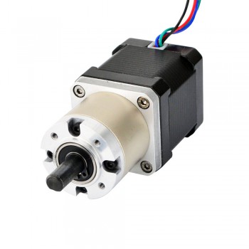
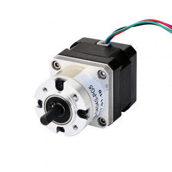
1.Ball Screw Driven Linear Stepper Motors:Ball screw driven linear stepper motors combine the advantages of precision ball screws and stepper motors. They utilize a ball screw mechanism to convert the rotary motion of the motor into linear motion. This type of linear stepper motor provides excellent precision, high thrust capability, and efficient operation. It finds applications in CNC machines, robotics, and industrial automation.
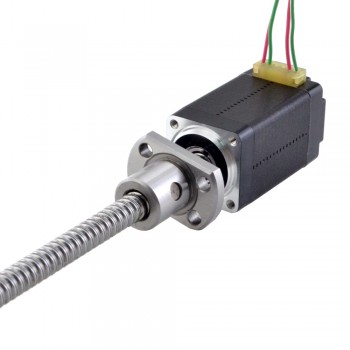
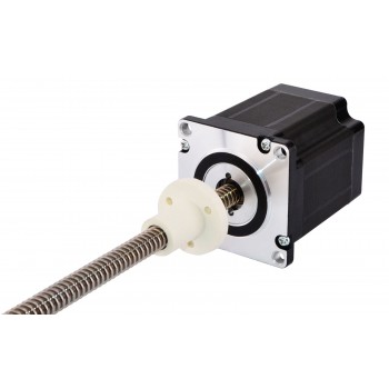
2.Lead Screw Driven Linear Stepper Motors:Lead screw driven linear stepper motors are similar to ball screw driven motors but use a lead screw instead. This makes them more cost-effective, suitable for applications that do not require extremely high precision. They are widely used in applications such as 3D printers, scanners, and medical equipment.
3.Linear Induction Motors (LIMs):Linear induction motors (LIMs) operate on the principles of electromagnetic induction. They consist of a primary winding, known as the primary reactance, and a secondary winding, known as the secondary reactance. When an alternating current is passed through the primary winding, a magnetic field is created, inducing current and a resultant magnetic field in the secondary winding. This interaction generates a force, propelling the secondary part in a linear direction. LIMs are utilized in transportation systems, levitation devices, and materials handling.
4.Linear Switched Reluctance Motors (LSRMs):Linear switched reluctance motors (LSRMs) are based on the concept of reluctance. They consist of a moving part, known as the translator, and one or more stator windings. By sequentially energizing the stator windings, a magnetic field is created that attracts the translator to a specific position. LSRMs are known for their simplicity, efficiency, and reliability. They are suitable for applications such as pumps, conveyors, and robotics.
5.Linear Hybrid Stepper Motors:Linear hybrid stepper motors combine the principles of permanent magnet stepper motors and variable reluctance stepper motors. They utilize a hybrid rotor design, with both permanent magnet and magnetic pole teeth. This hybrid design provides high torque, precise positioning, and improved stepping resolution. They are commonly used in medical equipment, semiconductor manufacturing, and positioning systems.

4.Protection methods of linear stepper motor
1.Adequate Enclosure and Protection:Linear stepper motors should be properly enclosed to prevent accidental contact with moving parts or energized coils. Additionally, installing protective covers or shields can further enhance the safety of the system. The enclosure and protection mechanisms should be designed to withstand the environmental conditions and anticipated forces during operation.
2.Regular Maintenance and Inspection:Regular maintenance and inspection of linear stepper motors are crucial to identify any potential issues that may compromise their safety. This includes checking for loose connections, damaged cables, worn-out components, and lubrication of moving parts. A well-maintained motor is less likely to malfunction or cause accidents.
3.Temperature Monitoring:Linear stepper motors can generate heat during operation, especially if they are subjected to continuous use or high loads. It is vital to monitor the motor’s temperature to prevent overheating, which can degrade performance and compromise safety. Temperature sensors and thermal management techniques such as cooling fans or heat sinks can be employed to maintain optimal operating conditions.
4.Overload and Overcurrent Protection:In industrial applications, linear stepper motors may encounter sudden load variations or excessive current flow. It is necessary to incorporate overload and overcurrent protection mechanisms to prevent damage to the motor or other connected components. These protective measures can include current limiters, fuses, or electronic control systems that monitor and regulate the motor’s current consumption.
5.Emergency Stop Functionality:An emergency stop (E-stop) button or switch should be incorporated into the linear stepper motor system to halt the operation immediately in case of an emergency or potential hazard. The E-stop function must be easily accessible and effectively cut off power to the motor, ensuring the safety of operators and preventing further damages.

Common applications and performance advantages of harmonic reducer gearbox

1.Brief introduction of harmonic reducer gearbox
A harmonic reducer gearbox is a type of high-precision gearbox that uses the principle of a strain wave to achieve high gear ratios in a compact, lightweight design. It consists of three main components: a wave generator (elliptical input), a flexspline (flexible, externally toothed cup), and a circular spline (rigid, internally toothed ring). The wave generator deforms the flexspline, causing its teeth to engage with the circular spline, and a large reduction ratio is achieved because the circular spline has more teeth than the flexspline.

2.Main working principles of harmonic reducer gearbox
1.Deformation: The wave generator rotates, causing the flexspline to deform into an elliptical shape.
2.Meshing: The deformation causes the teeth on the flexspline to engage with the teeth on the circular spline. Because of the elliptical shape, engagement only occurs at two points, usually on opposite sides of the gear.
3.Rotation: As the wave generator continues to spin, the points of engagement move along the circumference of both gears.
4.Reduction: Since the circular spline has more teeth than the flexspline, each full rotation of the wave generator causes the flexspline to advance by a small number of teeth relative to the wave generator. This difference in tooth count creates the gear reduction.
5.Backlash elimination: The preloaded, flexed engagement between the two gears eliminates play, resulting in near-zero backlash, a key advantage for high-precision applications like robotics and medical devices.

3.Main performance advantages of harmonic reducer gearbox
1.The transmission speed ratio of harmonic reducer from harmonic drive distributors is large. The speed ratio of single-stage harmonic gear transmission ranges from 70 to 320, which can reach 1,000 in some devices, and the speed ratio of multi-stage transmission can reach more than 30,000. It can be used not only for deceleration, but also for acceleration.
2.High bearing capacity. This is because the number of teeth meshed at the same time in the harmonic gear transmission is large, and the number of teeth meshed at the same time in the dual-wave transmission can reach more than 30% of the total number of teeth, and the flex wheel adopts high-strength materials, and the teeth are in surface contact.
3.High transmission precision. This is because the number of teeth meshed at the same time in the harmonic gear transmission is large, and the error is averaged, that is, the multi-tooth meshing has a mutual compensation effect on the error, so the transmission precision is high. In the case of the same gear accuracy level, the transmission error is only about 1/4 of the ordinary cylindrical gear transmission.
4.High transmission efficiency and smooth movement. Due to the uniform radial movement of the flex gear teeth during the transmission process, even if the input speed is high, the relative slip speed of the gear teeth is still extremely low (so it is a percent of the ordinary involute gear transmission) , Therefore, the gear tooth wear is small and the efficiency is high (up to 69%~96%).
5.The structure is simple, the number of parts is small, and the installation is convenient. There are only three basic components, and the input and output shafts are coaxial, so the structure is simple and the installation is convenient.
6.Small size and light weight. Compared with the general reducer, when the output torque is the same, the volume of the harmonic gear reducer can be reduced by 2/3 and the weight can be reduced by 1/2.
7.The movement can be transmitted to the confined space. Using the flexible characteristics of the flexible wheel, this valuable advantage of the wheel drive is unmatched by other existing drives.

4.Suitable applications of harmonic reducer gearbox
1.In industrial robots, the harmonic reducer gearbox can provide high-precision motion control to meet the precise positioning requirements of the robot joints. Its high reduction ratio and low noise characteristics enable the robot to maintain high precision and stability when performing complex operation tasks‌. For example, in welding robots, harmonic reducer gearboxes can precisely control the movement of robot arms to complete high-precision welding tasks.
2.In the aerospace field, harmonic reducer gearboxes are widely used due to their high reliability, lightweight and long life. Their wear-free design and precise control capabilities make them very suitable for working in extreme environments. For example, in satellite deployment systems, harmonic reducer gearboxes can be used to precisely control the attitude and position of satellites.
3.The field of medical devices, especially surgical robots and diagnostic equipment, requires high-precision and high-stability transmission systems. Harmonic reducer gearboxes are able to provide precise speed and position control to ensure the accuracy and reliability of medical equipment. Their low noise and aseptic operation characteristics also make them perform well in surgical environments. For example, in CT machines, harmonic reducer gearboxes can be used to drive rotating gantry to achieve high-precision scanning motion.
4.In automation equipment, the high efficiency and compact design of harmonic reducer gearboxes make them suitable for integration into space-constrained equipment. Their low noise and vibration characteristics also help improve the quality of the working environment. For example, on an automobile production line, a harmonic reducer gearbox can be used to drive conveyor belts and robots to achieve precise assembly of automobile parts.

What are the common problems of switching power supply?

1.What is switching power supply?
A switching power supply is an electronic power converter that efficiently changes voltage levels by rapidly switching a transistor on and off. It converts AC or DC input power into a regulated DC output, is much smaller and more efficient than a traditional linear power supply, and is used in everything from laptops to smartphones. The high-frequency switching allows for the use of a smaller transformer and filter, but can also create noise that requires filtering.

2.Working principle of switching power supply.
1.Input Rectification: The input AC power is first converted to a rough DC voltage using a rectifier circuit.
2.High-Frequency Switching: This DC voltage is then fed into a high-speed power transistor (like a MOSFET) that acts as a switch. It rapidly turns the voltage on and off, creating a high-frequency pulse train.
3.Voltage Transformation: The high-frequency pulses are sent through a small transformer to step the voltage up or down to the desired level. Using a high frequency allows for a smaller, more efficient transformer.
4.Output Rectification and Filtering: The high-frequency AC output from the transformer is again rectified into DC and then passed through filters to smooth out the remaining ripples, producing a stable DC output voltage.
5.Feedback Control: A control circuit constantly monitors the output voltage. If it deviates from the target, it adjusts the switching speed (the duty cycle) of the transistor to correct it, ensuring a stable output.

3.Main design advantages of switching power supply
1.High efficiency: Switching power supplies are significantly more efficient, with efficiencies up to 98–99%. This is because the switching transistors are either fully on or fully off, dissipating very little power. This efficiency leads to lower energy consumption and reduced operational costs.
2.Compact and lightweight: The high-frequency operation enables the use of smaller, lighter transformers and other components, resulting in a smaller overall size and weight. This makes them ideal for compact devices and allows for greater design flexibility.
3.Lower heat generation: Due to their high efficiency, less energy is lost as heat. This reduces the need for bulky cooling systems and improves reliability, as components operate at lower temperatures.
4.Wide input voltage range: They can be designed to operate over a wide range of input voltages, making them versatile for global use without needing different power adapters.
5.Versatility and power output: Switching power supplies can be designed as “boost” converters to produce an output voltage higher than the input voltage, a capability not possible with linear supplies. They can also provide high power output for larger applications.
6.Cost-effectiveness: Despite their complexity, the high efficiency and smaller size can make them more cost-effective, particularly for high-power applications.
7.Enhanced protection: They often include advanced protection features, such as overvoltage, overcurrent, and short-circuit protection, to safeguard the equipment and user.

4.Common problems of switching power supply
1.No Output, Good Fuse:One of the first things you should check when troubleshooting power supply issues is the fuse. If the fuse is intact but there is no output, the problem lies elsewhere. Common causes could include a malfunction in the control circuit or issues in the power regulation components, such as the rectifier diodes or smoothing capacitors.
2.Blown Fuse:A blown fuse is a clear indicator that something has gone wrong inside your switching power supply. The fuse is designed to protect the components from overload or short circuit. In general, a blown fuse suggests a problem with internal circuits. Voltage surges or fluctuations can cause a sudden current increase, leading to a blown fuse. To address this issue, you should inspect the rectifier diodes, high-voltage capacitors, and the power switch tube to look for signs of breakdown or damage.
3.No DC Output or Unstable Voltage Output:If the fuse is intact but you’re not getting the correct DC output or the voltage is unstable, several components may be at fault. The issue could stem from an open circuit, short circuit, overload, or failure in the auxiliary power supply. Additionally, breakdowns in high-frequency rectifiers or electric leakage in smoothing capacitors can cause these issues.
4.Poor Load Capacity:A power supply’s load capacity can degrade over time, especially in traditional units or those that have been in use for long hours. Aging components, unstable switching tubes, or inadequate cooling can result in poor load handling. In such cases, inspect the regulated diodes, rectifier diodes, and high-voltage smoothing capacitors to determine if any components are malfunctioning.
5.SMPS Partially Working:If your switching power supply seems to work intermittently or partially, the issue could be related to the high-frequency rectifier circuit, the control circuit, or protective features within the power supply. For instance, some power supplies may exhibit partial functionality when certain components, like the rectifier diodes or capacitors, fail but the rest of the circuitry is intact.
6.Audible Noise:Humming or buzzing noises emanating from your switching power supply are often a sign of underlying issues. Audible noise typically comes from components like transformers, capacitors, or fans. In some cases, this can indicate faulty capacitors, aging components, or mechanical interference.

Selection requirments of geared stepper motor

1.Basic introduction of linear stepper motor
A geared stepper motor is a combination of a stepper motor and a gearbox, which allows it to reduce speed while increasing torque. This makes it ideal for applications requiring high precision, high torque at low speeds, and fine positioning, such as robotics, CNC machinery, and 3D printers. Each pulse sent to the motor results in a precise, incremental step of rotation, making them very accurate and controllable.

2.Working principle of geared stepper motor
1.Electrical pulses: A stepper motor driver sends a sequence of electrical pulses to the motor’s coils (stator).
2.Rotor movement: Each pulse energizes a specific set of coils, creating a magnetic field that pulls the rotor into a new position, moving it by a fixed “step angle” (e.g., (1.8^{\circ })).
3.Precise control: The speed and angle of the motor are precisely controlled by the frequency and number of pulses sent by the controller.
4.Gearbox reduction: The motor’s output shaft is connected to a gearbox, which contains a series of gears.
5.Torque increase and speed decrease: The gearbox uses a specific gear ratio to reduce the speed of rotation while significantly increasing the torque at the output shaft.
6.Final output: The gearbox’s output shaft provides a motion that is slower, more powerful, and smoother for the connected load, such as a robotic arm or conveyor belt. 

3.Using advantages of geared stepper motor
1.Significantly Higher Torque Output:The gearbox multiplies the torque generated by the motor according to its gear ratio (N:1). For instance, a 50:1 gear ratio can boost the motor’s effective output torque by nearly 50 times (factoring in gear efficiency).This allows a relatively small motor to drive larger loads or overcome higher friction without requiring a larger, more expensive standard stepper motor.
2.Enhanced Resolution and Positioning Accuracy:A stepper motor has a fixed step angle (e.g., 1.8°). With a gearbox ratio of N:1, the output shaft’s effective step angle is reduced to 1/N of the original. For example, a 1.8° stepper motor with a 50:1 gearbox achieves a minimum step angle of 1.8°/50=0.036°, enabling ultra-fine motion control.The smaller effective step angle, combined with micro-stepping techniques, results in much smoother operation with less vibration at extremely low speeds.
3.Optimized Inertia Matching and Increased Rigidity:Inertia Ratio Reduction: Load inertia significantly impacts motor performance. When transmitted through the gearbox, the load inertia is reduced at the square of the gear ratio when reflected to the motor shaft. The mechanical rigidity provided by the gearbox makes the system less sensitive to variations in frictional load. It maintains stable positioning accuracy even in vertical drives or under changing friction conditions.
4.Resonance Avoidance and Smooth Operation: A Geared Stepper Motor operates the motor itself at a higher speed, while the output shaft runs slowly due to the gear reduction. This allows the motor body to bypass its inherent resonance frequency zone, resulting in smoother and quieter operation at the output.
5.Compactness and Cost-Effectiveness:The gearbox is usually integrated directly onto the motor’s rear, forming a compact unit. This saves installation space and simplifies mechanical design compared to using a separate high-torque motor or external gear reducer.

4.Selection requirments of geared stepper motor
1.Torque: Calculate the necessary holding and running torque, ensuring the final selection has a sufficient torque margin (at least 50%) to account for friction, wear, and resonance. High-torque applications are needed for heavy loads, while high-speed applications have lower torque requirements.
2.Speed: Determine the maximum speed and acceleration needed. This is critical for selecting a motor that can meet the dynamic demands without losing steps.
3.Accuracy and Positioning: Consider the required degree of accuracy, especially for applications like 3D printers or CNC machines, which may need high stop accuracy or closed-loop control.
4.Load Inertia: The motor’s torque-to-inertia ratio is important. A motor with a high ratio can accelerate and decelerate quickly. A larger load inertia will require a motor with a lower speed and higher torque.
5.Environmental Factors: Evaluate the operating environment for conditions such as temperature, humidity, and vibration, and select a motor with appropriate durability and special designs if necessary.
6.Torque and speed relationship: Remember that a motor’s output torque is inversely proportional to its speed. For high speed, choose a motor with low inductance; for low speed and high torque, choose a motor with high inductance and resistance.
7.Gearbox selection: Choose a gearbox that provides the correct gear ratio to achieve the required output speed and torque after the reduction.
8.Mounting and shaft: Ensure the physical dimensions of the motor and gearbox are compatible for mounting and that the motor shaft can properly connect to the gearbox.
9.Motor and drive compatibility: Ensure the motor is compatible with the chosen motor driver, considering voltage, current, and control method.
10.Control Method: Choose a suitable control method based on your application’s requirements, such as open-loop vs. closed-loop.
11.Safety and quality: Always add a safety factor for torque and consider a motor from a reputable manufacturer with a good reputation for quality and reliability.