Crucial factors to consider for worm reduction gearbox maintenance

1.Brief of worm reduction gearbox
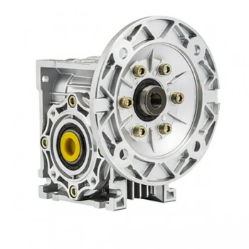
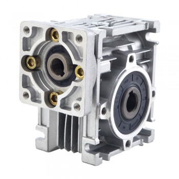
A worm reduction gearbox is a mechanical transmission system using a screw-like worm gear to mesh with a worm wheel for significant speed reduction and torque increase, operating on non-intersecting shafts at a 90-degree angle. Its compact design, high reduction ratios, and potential for self-locking make it ideal for applications like elevators, conveyors, and automated gates where holding a load is crucial.

2.Working principle of worm reduction gearbox
1.Input Rotation: The worm (input shaft) is connected to a motor or other power source and begins to rotate.
2.Meshing Interaction: The helical threads of the rotating worm engage with the teeth of the worm wheel.
3.Speed Reduction and Torque Amplification: As the worm turns, its threads push the worm wheel, causing it to rotate. Because the worm typically has only one or a few threads and the worm wheel has many teeth, the worm wheel rotates much slower than the worm, resulting in a significant speed reduction. This speed reduction is accompanied by a proportional increase in the output torque.
4.Self-Locking: The design creates significant friction and a unique angled engagement that prevents the worm wheel from being able to drive the worm in return. This self-locking feature is crucial for applications where loads need to be held in place.

3.Key advantages of worm reduction gearbox
1.High Torque Output:One of the principal advantages of worm reduction gearbox is their ability to deliver high torque output. The gear ratio in a worm gearbox can be accustomed to achieve major speed reduction, while simultaneously increasing the torque transmitted to the driven load.
2.Condensed and Space-Saving Design:Worm reduction gearboxes are known for their compactness. The small footprint makes them ideal for applications where space is restricted, such as in confined machinery or automated systems. Their compact design also makes it easier to integrate them into machinery with constrained space requirements, deprived of sacrificing performance.
3.Self-Locking Feature:One of the greatest prominent features of worm reduction gearboxes is their self-locking competence. This means that when the worm gear is not in motion, the worm wheel cannot rotate by itself. In other words, the gearbox stops back driving, which is the opposite rotation of the output shaft due to external forces acting on the system
4.Smooth and Noiseless Operation:Worm reduction gearboxes operate smoothly and silently due to the nature of the interlocking between the worm and worm wheel. Unlike spur gears, which can produce more noise and vibrations due to their direct tooth-to-tooth contact, the helical shape of the worm provides a steady arrangement, reducing friction and diminishing noise.
5.Well-organized Power Transmission:Even though worm gears are not as effective as other gear systems, they still provide a relatively high level of power transmission efficiency, particularly at low to moderate reduction ratios. The efficiency of a worm reduction gearbox is influenced by factors such as the material used, lubrication, and the number of threads on the worm.
6.Resourcefulness in Applications:Worm reduction gearboxes are versatile and can be used in a variety of applications across different industries. They are normally found in material handling systems like conveyors, automated doors, and lifts, as well as in lifting and hoisting equipment such as cranes and winches.

4.Crucial factors to consider for worm reduction gearbox maintenance
1.Lubrication:Lubrication is one of the most critical factors in the maintenance of worm gearboxes. It helps to reduce friction and wear between the worm gear and the worm wheel. Proper lubrication can help extend the lifespan of the gearbox and improve its performance. The type of lubricant used should be appropriate for the operating conditions and the gearbox design.
2.Inspection:Regular inspection of worm gearboxes is necessary to detect any signs of wear or damage. This can help to identify problems before they become severe and result in costly downtime. The inspection should include checking the teeth of the worm gear and the worm wheel, as well as the bearings and seals. Any signs of wear or damage should be addressed promptly to prevent further damage.
3.Temperature Monitoring:Worm gearboxes generate heat during operation. Excessive heat can cause the lubricant to break down, leading to increased friction and wear. It is essential to monitor the temperature of the gearbox regularly and ensure it remains within the recommended operating range. If the temperature exceeds the recommended range, the gearbox may need to be shut down until the cause of the problem is identified and addressed.
4.Cleaning:Proper cleaning of worm gearboxes is critical to prevent the buildup of dirt and debris, which can cause increased friction and wear. The gearbox should be cleaned regularly using appropriate cleaning agents and techniques. Care should be taken not to damage any gearbox components during cleaning.
5.Proper Storage:Proper storage of worm gearboxes is crucial when they are not in use. They should be stored in a dry, cool, and clean environment to prevent corrosion and other forms of damage. Before storing the gearbox, it should be cleaned, inspected, and properly lubricated.
6.Proper Installation:Proper installation of worm gearboxes is essential to ensure optimal performance and longevity. The gearbox should be installed in accordance with the manufacturer’s recommendations, using appropriate tools and techniques. Care should be taken not to damage any components during installation.

How to reasonably use the integrated servo motor?

1.What is a integrated servo motor?
An integrated servo motor is a compact, single unit that combines a servo motor, feedback device, and servo drive (electronics) into one housing. This all-in-one design eliminates the need for separate components and complex external wiring, simplifying installation and reducing space requirements in automated systems. Integrated servo motors offer high precision, efficiency, and are widely used in robotics, CNC machinery, and other automation applications due to their simplified integration and “plug-and-play” functionality.

2.Working principle of integarted servo motor
An integrated servo motor works on a closed-loop control principle, combining a motor, encoder, and drive into a single unit for high-precision motion. A higher-level controller sends motion commands, which the integrated unit’s internal controller processes to determine the required motor power. The encoder provides real-time feedback on the motor’s actual position and speed, which the drive uses to compare against the command and continuously adjust the power to the motor windings, correcting any errors and ensuring the motor moves exactly as commanded.

3.The importance of integrated servo motor
1.Simplified Design & Installation: The “all-in-one” design drastically reduces the number of components, cabling, and wiring, which simplifies installation and speeds up commissioning.
2.Space Savings: By integrating multiple components into a single unit, integrated servo motors significantly reduce cabinet space and allow for more compact machine designs.
3.Increased Reliability: Fewer external connections and cables mean fewer potential points of failure, reducing the likelihood of errors and leading to a longer service life.
4.Improved Performance: The synergistic integration of motor and drive allows for faster response times, superior torque density, and enhanced positioning accuracy.
5.Energy Efficiency: These systems are designed for optimal performance, consuming less power and converting more energy into useful work, which translates to lower energy costs.
6.Seamless Communication & Control: Advanced integrated servo motors support standard industrial communication protocols, allowing for smooth integration with other control systems, sensors, and fleet management software.
7.Reduced Maintenance: The reduction in external components and complexity leads to fewer maintenance requirements and less potential for downtime.
8.Broad Application: Their precision, reliability, and versatility make them crucial components in industries requiring high-accuracy motion control, including robotics, CNC machinery, packaging, and medical devices.

4.Methods of using integrated servo motor reasonably
1.Safety and Installation:Always connect the motor’s ground terminals to a robust ground connection to prevent electrical shock and ensure product safety.Install the motor in an industrial environment where it is protected from dust, corrosive gases, conductive objects, and fluids.Always turn off the main power and wait for the system to discharge completely before performing any wiring or inspections.The motor shaft should not bear loads exceeding its specified limits.
2.Setup and ConfigurationConnect the servo drive and motor correctly, ensuring the motor’s U, V, W terminals are not directly connected to an AC power supply. Use the manufacturer-provided PC software to modify parameters like subdivision values, then save and apply the changes by power cycling the unit. Set DIP switches for desired configurations, such as pulse modes (PUL/DIR, CW/CCW) and the pulse filter setting.
3.Control Mode Selection:Integrated servo motors typically offer position, speed, and torque control.Choose the mode that best suits your application; for example, use position mode for high-precision positioning requirements.
4.Tuning and Stability:Use the gain tuning panel to adjust control loop gains, which affects the system’s relative stability.While increasing stiffness can improve performance, be mindful of setting parameters too high, as this can lead to instability, oscillation, or vibration.
5.Power Supply Management:Ensure your power supply is robust enough for the motor’s load; a straining servo can cause the supply voltage to sag, leading to unpredictable behavior.For multiple servos, provide each one with a direct connection to the power supply to avoid affecting other servos if one draws significant current.

Methods for improving the accuracy of closed-loop stepper motors

1.Brief of a closed loop stepper motor
A closed-loop stepper motor system is a type of motor control that integrates an encoder feedback system with a standard stepper motor, enabling real-time position monitoring and adjustment to prevent step loss and improve accuracy, speed, and energy efficiency. This feedback allows the system to self-correct by continuously comparing the commanded position with the actual position, leading to a smoother, quieter operation with short settling times and higher torque, especially at low speeds, making it an attractive alternative to traditional open-loop steppers and even servo motors in many applications.

2.Main parts of a closed loop stepper motor
1.Stepper Motor:This is the core component that rotates in discrete steps. It includes a stator (the stationary part with coils) and a rotor (the rotating part with magnetic poles or teeth). In a closed-loop system, the motor’s rotor position is continuously monitored.
2.Encoder:This is the crucial feedback device that provides real-time information about the motor’s position and speed.
There are two main types:
Incremental encoders(Count pulses as the motor moves to determine relative position) and absolute encoders(Provide the exact position of the shaft at any given moment).
3.Motor Driver/Controller:This component receives commands from a higher-level controller or directly receives feedback from the encoder. It converts these signals into the correct electrical signals to drive the stepper motor. By comparing the commanded position with the position reported by the encoder, the driver can adjust the current to the motor to prevent lost steps, correct position errors, and optimize performance.

3.Methods for improving the accuracy of closed-loop stepper motors
1.Mechanical System Optimization:Minimize gaps in mechanical components like gears, lead screws, and couplings to prevent position errors, which can be done with high-precision, rigid mechanical systems.Use high-quality bearings and ensure proper alignment of components to create a more controlled motion path, leading to greater accuracy.
2.Motor and Feedback Selection:A motor with a smaller step angle provides finer angular displacement for a given number of pulses, improving resolution. Use an encoder with sufficient resolution and ensure it is placed at the actuator’s endpoint, not just the motor’s shaft, to get the most accurate position feedback.
3.Control System Enhancement:This is the core of a closed-loop system; the feedback device (like an encoder) provides real-time position data, allowing the controller to compare it with the command and make immediate adjustments to correct any errors.Divide each basic step into smaller microsteps to increase the motor’s resolution and smoothness, enabling more precise positioning.Implement sophisticated control algorithms that can dynamically adjust torque and compensate for factors like load variations, improving both position and velocity accuracy.
4.System Tuning and Maintenance:Regularly calibrate the motor and adjust parameters like current levels, acceleration/deceleration profiles, and microstepping settings to optimize performance.Identify and mitigate resonance frequencies that can cause vibrations and position errors by using notch filters in the motion controller.
5.Thermal Management:Stable Temperature: Keep the motor’s operating environment stable and ensure proper ventilation, heat sinks, or active cooling to prevent thermal-induced performance changes and accuracy issues.

4.Benefits of using closed-loop stepper motors
1.Enhanced Accuracy and Precision:Closed-loop stepper motors provide unmatched accuracy. The feedback system continuously monitors the motor’s position and corrects any deviations. This ensures precise movement, even in complex tasks. You can rely on these motors for applications requiring high precision, such as CNC machines or medical devices. The ability to maintain exact positioning reduces errors and improves overall performance.
2.Improved Reliability and No Step Loss:Step loss can disrupt operations and lead to costly errors. Closed-loop stepper motors eliminate this issue by using real-time feedback. The motor adjusts instantly to maintain its position, even under heavy loads. This reliability ensures smooth operation and reduces downtime.
3.High-Speed Performance and Torque Stability:Closed-loop stepper motors excel in high-speed applications. They maintain stable torque across a wide range of speeds. This makes them ideal for tasks requiring both speed and power. You can achieve faster production rates without sacrificing performance. The motor’s ability to handle varying loads ensures smooth and efficient operation.
4.Energy Efficiency and Reduced Power Usage:Energy efficiency is one of the key benefits of using closed-loop stepper motors. These motors adjust their power consumption based on the workload. This reduces energy usage and lowers operating costs. You can achieve significant savings while maintaining high performance. The efficient design also minimizes heat generation, extending the motor’s lifespan.
5.Adaptability to Dynamic Loads:Closed-loop stepper motors adapt quickly to changing conditions. The feedback system allows the motor to respond to dynamic loads in real time. This adaptability ensures consistent performance, even in demanding environments. You can use these motors in applications with variable workloads, knowing they will deliver reliable results.

The development trends of linear stepper motor

1.Understanding linear stepper motors
Linear stepper motors, also known as linear actuators, are electrical devices that convert electrical energy into precise linear motion. They are a type of stepper motor, which is a digital electromechanical device that divides a full rotation into a number of equal steps. Unlike rotary stepper motors that generate rotational motion, linear stepper motors produce linear movements along a defined axis. This makes them ideal for applications requiring precise positioning, such as robotics, CNC machines, 3D printers, and medical devices.

2.The operation principle of linear stepper motor
In a linear stepper motor, the stator windings are energized in a predetermined sequence by an electronic control system, often referred to as a stepper motor driver. The driver provides the necessary electrical pulses to the windings, causing them to produce magnetic fields that interact with the rotor. By controlling the timing and sequence of these electrical pulses, the driver determines the direction and distance traveled by the rotor.The most common types of sequences used in linear stepper motors are full-step, half-step, and microstep. The most common types of sequences used in linear stepper motors are full-step, half-step, and microstep.

3.Key features of linear stepper motor
1.High Precision Motion Control:Linear stepper motors are known for their high precision motion control capabilities. They are designed to move in a straight line with accuracy and repeatability, making them ideal for applications that require precise positioning. With the ability to control the movement of the motor in small increments, linear stepper motors can achieve precise positioning in applications such as 3D printing, CNC machining, and robotics.
2.Quiet Operation:One of the key features of linear stepper motors is their quiet operation. Unlike other types of motors that produce noise during operation, linear stepper motors operate silently, making them ideal for applications where noise levels need to be kept to a minimum. This feature is particularly important in industries such as medical devices, semiconductor manufacturing, and optics, where noise can interfere with sensitive operations.
3.High Acceleration and Deceleration:Linear stepper motors are capable of high acceleration and deceleration, making them suitable for applications that require rapid changes in speed and direction. This feature is essential in industries such as aerospace, automotive, and industrial automation, where fast and precise motion control is crucial for increasing productivity and efficiency.
4.Flexible Integration:Linear stepper motors are highly versatile and can be easily integrated into a wide range of applications. They come in various sizes and configurations to meet different requirements, making them suitable for diverse industries such as aerospace, automotive, medical devices, and packaging.

4.The development trends of linear stepper motor
1.Increased Efficiency and Performance:One of the key innovations in linear stepper motors is the focus on increasing efficiency and performance. Manufacturers are constantly looking for ways to improve the power and speed of linear stepper motors while reducing energy consumption. This has led to the development of new motor designs, better materials, and more advanced control systems.
2.Integration of Smart Technologies:Another trend in the world of linear stepper motors is the integration of smart technologies. With the rise of the Internet of Things (IoT) and Industry 4.0, manufacturers are looking to incorporate sensors, communication interfaces, and data analytics capabilities into their linear stepper motors. This allows for real-time monitoring, predictive maintenance, and remote control, enabling better performance and efficiency.
3.Miniaturization and Compact Designs:In recent years, there has been a trend towards miniaturization and compact designs in linear stepper motors. With advancements in materials and manufacturing processes, manufacturers are able to create smaller and lighter motors without compromising on performance. These miniaturized linear stepper motors are ideal for applications where space is limited, such as in medical devices, robotics, and consumer electronics.
4.Greater Customization and Flexibility:Customization and flexibility have also been key trends in the development of linear stepper motors. Manufacturers are now offering a wide range of customizable options, including motor size, shape, winding, and control features. This allows customers to tailor linear stepper motors to their specific requirements, whether it’s for a high-precision application, a high-speed application, or a high-torque application.
5.Improved Sustainability and Environmental Impact
As the demand for greener and more sustainable technologies grows, manufacturers are focusing on improving the sustainability and environmental impact of linear stepper motors. This includes using eco-friendly materials, reducing energy consumption, and implementing recycling programs for old motors. By making linear stepper motors more sustainable, manufacturers are not only reducing their carbon footprint but also meeting the increasing demand for environmentally friendly products.