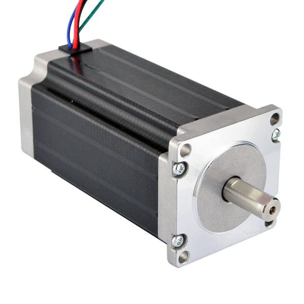
Generally, the driving direction and pulse signal of the cheap stepping motor have certain requirements. For example, the driving direction of the rising or falling direction of the first pulse signal is different before the recognition of a few microseconds, otherwise there will be a pulse operation angle and rotation instead of the actual Need, the final failure phenomenon is the wider the walk, the more obvious the subdivision, the solution is mainly to use software to change the logic of hair, pulse or delay.
Since the characteristics of the stepper servo motor determine that the initial speed cannot be too high, especially in the case of a large load inertia, it is recommended that the initial speed be lower than 1 r / s. In this case, the impact is small and the system is subject to too much acceleration, which is easily overshooted, resulting in inaccurate positioning. There should be a certain pause between the forward and reverse rotation of the motor. Otherwise, the overshoot will be caused by an excessive reverse acceleration.

- Adjust the value of the compensation parameter according to the actual situation. Since the elastic deformation of the timing belt is large, some compensation should be added when changing the direction.
- Appropriately increase the motor current and increase the drive voltage. Select a motor with a higher torque.
- System interference causes the controller or driver to malfunction, so we can only find the source of interference, reduce its interference ability, cut off the transmission path, and improve its anti-interference ability.
Common measures:
A. Replace the ordinary wire with a double shielded wire. The signal lines in the system are respectively connected to high current or high voltage conversion lines to reduce electromagnetic interference.
B. Use a power filter to filter out interference waves from the grid and add a line filter at the input of the main power-consuming device to reduce interference between devices in the system when conditions permit.
C. It is preferred to transmit signals between devices through an opto-isolator. Where permitted, the pulse and direction signals are preferably transmitted differentially by optical isolation. By adding a resistor-capacitor absorption or fast-release circuit at both ends, the inductive load can generate 10-100 times the peak voltage at the beginning of the inductive load.
https://mytrendingstories.com/member/jeffery-alan/
https://www.global-gathering.com/opinions/706