Posted on Leave a comment

Stepper Motor Settling Time (Ringing) and Resonance

When the stepper motor receives the final pulse signal, (either one or from a continuous train), it will stop rotating. However, complete rest will not occur until all the oscillations have stopped. The time it takes from the application of the last pulse received until the stepper motor comes to a complete rest is known as settling time. (See graph below). Resonance occurs when the stepper motor suddenly makes large oscillations, or the output torque suddenly drops at one certain pulse rate or numerous small regions of pulse rates. The stepper motor will stop (stall), may miss steps or reverse direction from the commanded direction. This phenomenon occurs when the natural frequency of the stepper motor coincides with the frequency of the input pulse rate. This generally occurs around 100 – 200 pulses per second in a full-step operation, and also at higher pulse rates. Microstepping half-step operation, or electrical or mechanical damping, can reduce resonance issues. Microstepping has a large effect on settling time and resonance due to the smaller angular displacement taken per pulse. See Figure below.

Resonance Characteristics
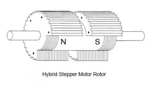
Since a hybrid stepper motor system is a discreet increment positioning system, it is subject to the effect of resonance. Where the system is operated at this given frequency, it may begin oscillating. The primary resonance frequency occurs at about one revolution per second. Oscillating will cause a loss of effective torque and may result in a loss of synchronism. Settling time and resonance can be best dealt with by dampening the stepper motor’s oscillations through mechanical means. Mechanically, a friction or viscous damper may be mounted on the stepper motor to smooth out the desired motion.

Methods for Changing or Reducing Resonance Points:
• Use of Gearboxes or Pulley Ratios
• Utilize Microstep Drive Techniques
• Change System Inertia
• Accelerate Through Resonance Speed Ranges
• Correct Coupling Compliance

General Stepper Motor Driver Safety Considerations

Posted on Leave a comment

Tips on Selecting and Sizing Geared Stepper Motors

In this post, I’ll describe the process I use for sizing gearboxes and geared stepper motors.

To make the selection, I am using KEB’s software sizing program called KEB-DRIVE. KEB-DRIVE is free and easy to use. If interested to follow along, you can download a copy of the software.

gearmotor sizing

2. Select the correct gear technology for the application
Configurations in KEB-Drive start at the top left. On the left, you’ll see drop-downs to select different gear types and sizes.

3.Motor Selection (Size, voltage, frequency)
Working to the right, I then select the size of the motor I want. Options for both Induction motors and AC Servo motors are listed. Here is a comparison of the advantages between servo and induction motors.

4.Adjust the Torque/Speed selection
Is it a speed reducer? Or a torque Increaser? It’s both – higher gear ratios will provide lower output speeds and higher torques. Use the drop down to see all the different possible configurations with the selected gearbox/motor combo.

5. What is the gearing Service Factor and why is it important?
The gearing service factor (SF) is the ratio between the:
A SF of 1.0 means the gears will have a nominal output torque equal to that of their rating. Selecting a motor/gear configuration with a SF of less than 1.0 is not advised. This means the gears will be undersized when operated at the nominal point. This could also indicate that the motor selected is too large.

6.Select gearmotor options (mounting style)
This section allows a user to select how the geared motor will be mounted. The flexibility of mounting is one reason that the KEB integral gearmotor solution has been so popular. Users can select a unit with an output shaft. Or a shaft mounted unit with a hollow bore. Mounting feet and mounting flanges can also be selected.

Posted on Leave a comment

Somthing about gear reduction stepper motor

Geared stepper motors are perfect solutions for low speed and high torque positioning applications. GEMS provide NEMA size stepper motors that are paired with planetary gearbox and spur gearbox. Our design incorporates a square bodied motor and an round shape planetary stepper motor gearbox into a compact and cost-effective package. Our geared stepper motors are offered in six NEMA frame sizes (from NEMA 8 to NEMA 42) and each NEMA size motor has an integrated stepper motor gearbox with a wide range of gear ratios (from 1:3.7 to 1:369) so as to deliver any desired torque and speed combinations for your applications. The dual shaft version is available for you to install the brake, shaft coupler or an encoder where you need to keep track of the shaft position. 8-lead motor is aslo available upon request for all possible wiring configurations: bipolar, unipolar, series, or parallel. For higher speed and better speed control capability, please check out our brushless gear motors.

1.8° NEMA 8 GEARED STEPPER MOTOR WITH PLANETARY GEARBOX
NEMA8 is our smallest size of geared stepper motor. The 22mm diameter planetary stepper motor gearbox has gear ratio from 1:3.7 to 1:369. The gearbox output torque is up to 143 oz-in (1 Nm).

gear reduction stepper motor

geared stepper motor for sale


TABLE 1. MOTOR SPECIFICATIONS
Model Length L Rated Current Resistance Inductance Holding Torque Holding Torque Rotor Interia Lead wires Weight
mm A Ω/Phase mH/Phase Oz.in N.m g.cm2 g
17hs19-2004s 30 0.5 4.8 1.3 2.6 0.018 2.5 4 50
17hs162004s 42 0.5 7.5 2.4 3.6 0.025 4.5 4 90
TABLE 2. GEARBOX SPECIFICATIONS
Number of gear trains 1 2 3 4
Gear ratio 3.7, 5.2 14, 19, 27 51, 71, 100, 139 189, 264, 369
Length L2 mm 24.4 33 41.5 49.8
Rated output torque N.m 0.6 1 1.6 2
Max output torque N.m 1.8 3 4.8 6
Efficiency % 90 81 73 66
Weight g 35 45 55 65

Posted on Leave a comment

Open-loop vs. closed-loop stepper systems

First let’s explore how high performance closed-loop stepper motor system compare to traditional open-loop stepper systems in terms of torque and efficiency.

There’s superior performance from closed-loop stepper systems over open-loop setups as demonstrated in laboratory test results comparing the two systems’ acceleration (torque), efficiency (power consumption), position error (accuracy), heat generation, and noise levels. Just consider the relationship between torque and acceleration. Torque-speed curves show the peak and continuous torque ranges of a closed-loop stepper system alongside the usable torque range of an open-loop stepper system. Very often, torque in the real world translates into acceleration — so motors with greater torque can accelerate a given load faster.

To test this difference in torque performance in the lab, equally sized open-loop and closed-loop step motor systems get identical inertial loads. Programming commands the two systems to perform identical move profiles, except that acceleration rate and top speed are slowly increased in each system until they make positioning errors.

open-loop vs. closed-loop system

Here we have a move profile comparison between a open-loop vs. closed-loop system. This is a comparison between that from a StepSERVO closed-loop system and that from an open-loop system. The closed-loop system (due to its higher torque producing capability) gets a maximum acceleration rate of 2,000 rev/sec2 and a top speed of 20 rev/sec (1,200 rpm)
as seen here.

Say that the open-loop system gets a maximum acceleration rate of 1,000 rev/sec2 and a top speed of 10 rev/sec (600 rpm). This top speed of 10 rev/sec correlates to where the flat portion of the torque-speed curve ends. The closed-loop system (due to its higher torque producing capability) gets a maximum acceleration rate of 2,000 rev/sec2 and a top speed of 20 rev/sec (1,200 rpm). This is double the performance of the open-loop system and cuts the move time nearly in half — from 110 msec down to 60 msec.

For applications requiring high throughput (such as indexing, edge guide positioning and pick-and-place systems) the closed-loop stepper motor driver system provides a clear performance advantage.

Posted on Leave a comment

Tips on Selecting A Stepper Motor Driver

Amount, speed, and direction of rotation of a stepper motor are determined by the appropriate configurations of digital control devices. Selecting the most compatible stepper motor, driver, and/or controller, can save the user money and be a less cumbersome motion control solution. Anaheim Automation categorizes the major types of digital control devices as:

Image result for stepper motor

• Stepper Motor Drivers – offered in full-step, half-step and micro-step analog stepper driver
• Stepper Motor Controllers (sometimes referred to as Control Links – controllers indexers, and pulse generators sold separately or in Drivers Packs
• Stepper Motor Driver Packs – packaged units that include drivers and optional controller, with a matched power supply (most models are enclosed units that are fan-cooled)
• Integrated Stepper Motor/Driver/Controllers – packaged at the end of a stepper motor are drivers and simple controllers (only available for high-torque stepper motors)

These devices are employed as shown in Figure 5. The stepper motor driver accepts clock pulses and direction signals and translates these signals into appropriate phase currents in the stepper motor. The Indexer creates the clock pulses and direction signals, “translates” them into power to energize the stepper motor windings. The computer or PLC (programmable logic controller) sends commands to the indexer/controller.

Load characteristics, performance requirements, and mechanical design including coupling techniques must be thoroughly considered before the designer can effectively select the most suitable stepper motor and driver combination for a specific application. Failure to do so may result in poor system performance, or cost more than necessary. The following factors must be considered in order to obtain an optimum stepper motor motion control solution:

Why do you use a stepper motor?

Posted on Leave a comment

General Stepper Motor Driver Safety Considerations

The following safety considerations must be observed during all phases of operation, service and repair. Failure to comply with these precautions violates the safety standards of design, manufacture and intended use of the product(s). Anaheim Automation assumes no liability for the customer’s failure to comply with these requirements, and advises the misuse of its stepper motor products will void the warranty. Even well-designed and manufactured products, operated and installed improperly, can be hazardous. Safety precautions must be observed by the user with respect to the load and operating environment. Described briefly are general Safety Considerations. Please refer to the Environment Consideration’s Guide for more details.

Image result for stepping motor

•Use caution when handling, testing, servicing and adjusting during all phases of installation and operation of a stepper motor system
•No service/maintenance should be performed with power applied
•Exposed circuitry should be properly guarded or enclosed to prevent unauthorized human contact with live circuitry
Stepper motor drivers/controllers should be securely mounted and adequately grounded
•Provide adequate air flow and heat dissipation for all stepper motor system components
•Do not operate a stepper motor system in the presence of flammable gases, dust, vapor or liquids

IMPORTANT NOTE: The customer is responsible for the proper selection, installation, and operation of the stepper motor products purchased from Anaheim Automation. The customer must determine the fitness of selected products for a specific application. Although it is the company’s intention to provide sound advice and accurate documentation, Anaheim Automation assumes no liability in the suggestions it offers.

Posted on Leave a comment

Detailed description of the two motors

A stepper motor is a motor controlled by a series of electromagnetic coils. The center shaft has a series of magnets mounted on it, and the coils surrounding the shaft are alternately given current or not, creating magnetic fields which repulse or attract the magnets on the shaft, causing the motor to rotate. There are two basic types of stepper motors, unipolar steppers and bipolar steppers.

Unipolar Stepper Motors

The unipolar stepper motor for sale has five or six wires and four coils (actually two coils divided by center connections on each coil). The center connections of the coils are tied together and used as the power connection. They are called unipolar steppers because power always comes in on this one pole.

To control the stepper, apply voltage to each of the coils in a specific sequence. The sequence would go like this:

unipolar stepper motor for sale

Bipolar stepper motors

The bipolar stepper motor for sale usually has four wires coming out of it. Unlike unipolar steppers, bipolar steppers have no common center connection. They have two independent sets of coils instead. You can distinguish them from unipolar steppers by measuring the resistance between the wires. You should find two pairs of wires with equal resistance. If you’ve got the leads of your meter connected to two wires that are not connected (i.e. not attached to the same coil), you should see infinite resistance (or no continuity). Like other motors, stepper motors require more power than a microcontroller can give them, so you’ll need a separate power supply for it. Ideally you’ll know the voltage from the manufacturer, but if not, get a variable DC power supply, apply the minimum voltage (hopefully 3V or so), apply voltage across two wires of a coil (e.g. 1 to 2 or 3 to 4) and slowly raise the voltage until the motor is difficult to turn. It is possible to damage a motor this way, so don’t go too far.

To control a bipolar stepper motor, you give the coils current using to the same steps as for a unipolar stepper motor. However, instead of using four coils, you use the both poles of the two coils, and reverse the polarity of the current.

bipolar stepper motor for sale

So for examples, if you have a 1.8-degree stepper, and it’s turned 200 steps, then it’s turned 1.8 x 200 degrees, or 360 degrees, or one full revolution. In every step of the sequence, two wires are always set to opposite polarities. Because of this, it’s possible to control steppers with only two wires instead of four, with a slightly more complex circuit. The stepping sequence is the same as it is for the two middle wires.

Posted on Leave a comment

How to use the dc motor & stepper driver with guidence

Motors make the world spin around, and now you can easily control motors with digital stepper motor driver and the dc Motor & Stepper driver!  Simple dc motors can moved forwards and backwards, perfect for moving the wheels on a robot or vehicle.  Stepper motors can precisely move in small increments, like moving the nozzle of a 3D printer up and down with millimeter accuracy. Since the motor only uses the I2C (SDA & SCL pins), it works with any and all Feathers. For this reason, stepper motors are the motor of choice for many precision motion control applications. Stepper motors come in many different sizes and styles and electrical characteristics. This guide details what you need to know to pick the right motor for the job. In this lesson you will learn how to control a stepper motor using your pi and the same motor control chip that you used with the dc motor in this part.

digital stepper motor driver

The part will also show you how to use an alternative driver chip, the ULN2803.For this project, it does not really matter if you use a L293D or a ULN2803. The lower cost of the ULN2803 and the four spare outputs, that you could use for something else, probably make it the best choice if you don’t have either chip. The motor is quite low power and suffers less from the surges in current than dc motors and servos (which use DC motors). The original hybrid stepper motor is one of our most beloved shields, which is why we decided to squish it all together on a motor to make something even smaller, lighter, and more portable! Instead of using a latch and the Arduino’s PWM pins, we have a fully-dedicated PWM driver chip onboard. This chip handles all the motor and speed controls over I2C.

hybrid stepper motor

This project will therefore work okay powered from the 5V line of the Raspberry Pi, as long as the Pi is powered from a good supply of at least 1A. Comes with an assembled & tested Feather Wing, terminal blocks & plain header. Some soldering is required to assemble the headers on. Stacking headers not included, but we sell them in the shop so if you want to stack shields, please pick them up at the same time. Feather and motors are not included but we have lots of motors in the shop. You can use any DC or stepper motors that run from 4.5-13.5VDC and draw under 1.2A per coil. You’ll likely also need to provide some external power supply for your motors, since its not suggested you run motors from the Feather’s lipoly battery. For a healthy culture and delicious tasting ‘buch you’ll need to maintain a pretty high temperature (~77F/25C) while brewing (5-7 days). Keeping the brew that warm is challenging in colder climates. With a little help from a terrarium heater and some electronics, I created a thermostat for brewing year round.

Posted on Leave a comment

Overview the Stepper Motor

There are three basic types of step motors: variable reluctance, permanent magnet, and hybrid. This discussion will concentrate on the hybrid stepper motor, since these step motors combine the best characteristics of the variable reluctance and permanent magnet motors. They are constructed with multi-toothed stator poles and a permanent magnet rotor. Standard hybrid motors have 200 rotor teeth and rotate at 1.8º step angles. Because they exhibit high static and dynamic torque and run at very high step rates, hybrid step motors are used in a wide variety of commercial applications including computer disk drives, printers/plotters, and CD players. Some industrial and scientific applications of stepper motors include robotics, machine tools, pick and place machines, automated wire cutting and wire bonding machines, and even precise fluid control devices.

17HS24-2104S

HALF STEP—half step simply means that the step motor is rotating at 400 steps per revolution. In this mode, one winding is energized and then two windings are energized alternately, causing the rotor to rotate at half the distance, or 0.9°. Although it provides approximately 30% less torque, half-step mode produces a smoother motion than full-step mode.

FULL STEP—standard hybrid stepping motors have 200 rotor teeth, or 200 full steps per revolution of the motor shaft. Dividing the 200 steps into the 360° of rotation equals a 1.8° full step angle. Normally, full step mode is achieved by energizing both windings while reversing the current alternately. Essentially one digital pulse from the driver is equivalent to one step.

Linear Motion Control—the rotary motion of a stepper motor can be converted to linear motion using a lead screw/worm gear drive system. The lead, or pitch, of the lead screw is the linear distance traveled for one revolution of the screw. If the lead is equal to one inch per revolution, and there are 200 full steps per revolution, then the resolution of the lead screw system is 0.005 inches per step. Even finer resolution is possible by using the step motor/drive system in microstepping mode.

NEMA 17 StepperThe stepper motor for sale driver receives step and direction signals from the indexer or control system and converts them into electrical signals to run the step motor. One pulse is required for every step of the motor shaft. In full step mode, with a standard 200-step motor, 200 step pulses are required to complete one revolution. The speed of rotation is directly proportional to the pulse frequency. Some drivers have an on-board oscillator which allows the use of an external analog signal or joystick to set the motor speed. The choice of a step motor depends on the application’s torque and speed requirements. Use the motor’s torque-speed curve (found in each drive’s specifications) to select a motor that will do the job. Every stepper drive in the line shows the torque-speed curves for that drive’s recommended motors. If your torque and speed requirements can be met by multiple step motors, choose a drive based upon the needs of your motion system- step/direction, stand-alone programmable, analog inputs, microstepping- then choose one of the recommended motors for that drive. The recommended motor list is based on extensive testing by the manufacturer to ensure optimal performance of the step motor and drive combination.

Posted on Leave a comment

Something About NEMA 17 Motor for 3D Printers

Stepper motors are brushless motors that use multi-toothed electromagnets to define the position. The electromagnets are fixed around a centralized gear. NEMA numbers define the standard dimensions of a faceplate for mounting a motor. NEMA 17 stepper motors for sale are stepper motors with a 43.2mm x 43.2mm (1.7 inch x 1.7 inch) faceplate. They are heavier and larger than a NEMA 14, but their size is what ensures more room for higher torque. NEMA 17 is the most common size for stepper motors used in 3D printers. They can be designed and manufactured to have different mechanical and electrical specifications to suit the 3D printer that you want to build.

NEMA 17 Stepper

When looking for a NEMA 17 stepper, remember that the name is merely the frame size standard, which defines the dimensions of a mounting faceplate. You need to make sure that you are getting the right stepper based on the motor’s electrical specifications. A high torque NEMA 17 stepper that can provide 200 steps per revolution (1.8-degree step angle) is one of the options to consider for 3D printers. Be sure to check the model and specifications of your 3D printer before you buy a NEMA 17.

17HS24-2104S

Some companies can manufacture and design custom NEMA 17 stepper motors for your 3D printer. The service comes with custom winding and housing to suit specific dimensional and application needs. You can choose different lead wires and include lubricant and bearing options in case you need parts for high temperature and humid operations.

Nema Size 17 Stepper Motor for DIY 3D Printer CNC Rob

Custom NEMA 17 stepper motors are ideal for custom 3D printer applications that require a specific lead length, shaft size, frame size, or body length. You can buy NEMA 17 steppers online. Look for a reputable supplier of small electric motors with years of experience working for a range of industries. This way, you can be sure to get high-quality stepper motors at the right size and at a reasonable price.