1.Concepts of linear stepper motor
A linear stepper motor is a high-precision electromechanical actuator that directly converts electrical pulse signals into fixed incremental linear motion, rather than rotational motion like traditional rotary stepper motors. It eliminates the need for intermediate mechanical transmission components (e.g., ball screws, gear racks) to realize linear displacement, making it ideal for applications requiring accurate positioning and rapid response.
2.Core mechanical elements of linear stepper motor
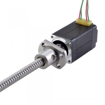
1.Stator: A stationary outer ring housing electromagnetic coils (windings). When energized in sequence, these coils generate magnetic fields that drive the motor’s internal motion.
2.Rotor: The rotating internal part, typically containing permanent magnets and toothed silicon steel laminations. In a linear stepper, the rotor often functions as a precision nut.
3.Lead Screw: A threaded rod that replaces the standard motor shaft. As the rotor-nut rotates, it drives the lead screw forward or backward along a straight path.
4.Anti-Rotation Mechanism: Essential for converting rotational force into linear travel. Depending on the motor type, this is either built into the housing (captive) or required as an external guide (non-captive).
5.Bearings: High-quality ball bearings support the rotor to ensure smooth, low-friction operation and extend the motor’s lifespan.
3.Performance advantages of linear stepper motor
1.Step-wise Displacement Control: Each electrical pulse corresponds to a fixed linear step pitch (usually μm-level resolution). The position is directly determined by the number of pulses, realizing open-loop precise positioning without additional position sensors (e.g., encoders) for most low-load scenarios.
2.Excellent Repeatability: The repeat positioning accuracy can reach ±1~±5 μm. There is no transmission backlash caused by mechanical components (such as ball screw gaps), which is especially suitable for high-precision reciprocating motion scenarios (e.g., semiconductor wafer handling, 3D printer Z-axis drives).
3.No Intermediate Transmission Components: It directly converts electrical pulses into linear motion, eliminating the need for ball screws, gear racks, couplings and other transmission mechanisms. This avoids transmission errors, wear and noise caused by mechanical components.
4.Quick Start/Stop & Reversal: The mover has a small mass and low inertia. It can complete start, stop and reverse actions in a short time, and is suitable for short-stroke, high-frequency reciprocating motion (e.g., SMT pick-and-place machines, precision dispensing pumps).
5.Static Holding Force Without Power Supply: When the motor is powered off, the stator winding still has residual magnetism, which can provide a certain static holding force to prevent the mover from slipping under load. This is suitable for scenarios requiring position locking (e.g., precision positioning stages).
6.Open-loop Control Capability: The traditional open-loop control mode does not need complex feedback circuits, and the control system is composed of a stepper motor driver and a controller (PLC/microcontroller), which has low hardware cost and easy programming.
7.Energy Consumption Matching Load: The motor only consumes power when moving, and the static holding state consumes low power. Compared with hydraulic/pneumatic linear actuators, it saves more energy and is more environmentally friendly.
4.Design difficulties of linear stepper motor
1.Dimensional Accuracy: Operating temperatures can rise by over 135°F (57°C), causing materials like plastic threads in the rotor to expand significantly more than metal journals (up to .004″ vs .001″). If not precisely managed, this expansion can cause the rotor to rub against the stator wall.
2.Component Degradation: High heat can degrade wire insulation and weaken internal magnets, directly reducing motor torque and efficiency.
3.Critical Frequencies: Resonance occurs if the stepping frequency matches the motors natural frequency (typically around 100–200 pulses per second), leading to audible noise, lost steps, or even total stalling.
4.Damping Complexity: Designers must implement mechanical dampers or complex algorithms (like S-curve profiles) to “smooth out” these vibrations, though higher-order algorithms can introduce their own numerical precision issues and computational burdens.
5.Backlash and Wear: Over time, the axial movement between the screw and nut (backlash) increases due to wear. Designers must often use specialized clearance nuts or anti-backlash designs that sacrifice some efficiency for long-term precision.
6.End Fixity and Buckling: Long lead screws are sensitive to “column loading,” where the screw may buckle under compression if the length is not perfectly balanced with its diameter and speed.
7.Concentricity Issues: Achieving perfect alignment (concentricity) between the internal nut and the lead screw is vital; even minor misalignment can cause severe radial impact forces that destroy bearings or lead screws.
8.Miniaturization Limits: As motors shrink (e.g., micro-steppers for medical use), the magnetic flux density becomes too small to generate usable torque, posing a hard physical limit on how small these devices can realistically be.
9.Electromagnetic Interference (EMI):Operating at the high frequencies required for microstepping can generate significant EMI, which can interfere with nearby sensitive electronics, such as those found in medical or aerospace sensors.