Posted on Leave a comment

How does a closed-loop stepper Motor work?

Stepper motors are inherently open-loop devices. They don’t require feedback because each pulse of current delivered by the drive equals one step of the motor (or a fraction of a step in the case of microstepping). Plus with small step sizes (or step angles) the motor’s position can be determined very precisely without the need for a feedback device and complicated control schemes.

So, if a stepper motor’s position can be determined in an open-loop system, why would you add the cost and complexity of closed-loop control to a stepper motor?
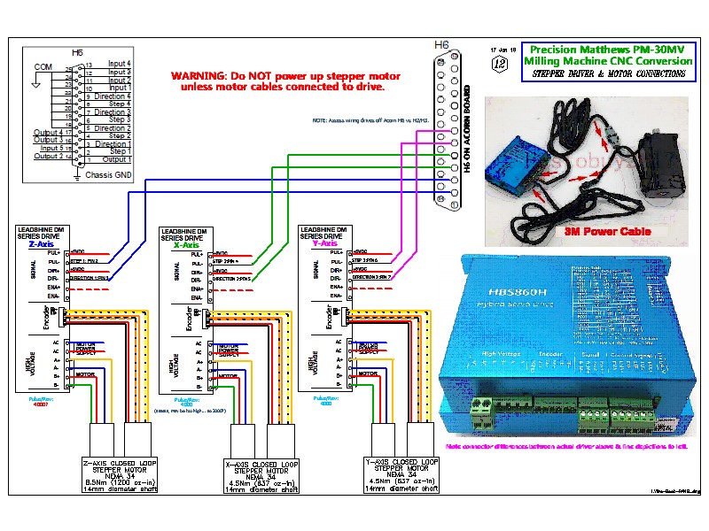
How does a closed-loop stepper Motor work?

There are generally three types of closed-loop control for stepper motors, each offering a different level of positioning control and complexity.

Step-loss compensation: Reactive position correction at the end of the move
The most common type of closed-loop stepper system is based on step-loss compensation, also referred to as step-loss control or stepper position maintenance. In this setup, the drive operates in microstepping mode, and an encoder tracks the shaft (or load) position. If lost steps are detected, based on the commanded position (number of steps multiplied by step angle) versus the actual position read by the encoder, the controller commands additional steps so the motor (or load) reaches the desired position.

Load position control: Continuous, real-time position correction without complex controls
Load position control, also referred to as closed-loop microstepping, continuously monitors the shaft (or load) position and generates an error signal. The controller uses this error signal to adjust the commands in real-time, during the entire move profile.

Servo control: Complete control of torque and position
The most advanced closed-loop stepper control method is to operate the motor as a two-phase brushless (BLDC) motor. (Note that many stepper motors have two phases offset by 90° whereas brushless dc motors have three phases offset by 120°.) This method is referred to as servo stepper or closed-loop stepper control.

Stepper motor systems using closed-loop control represent a small percentage of stepper motor applications, but if loss of position could be catastrophic to the application, yet the system requires high torque at low speed, relatively simple architecture, and relatively low cost (compared to a true servo motor system) a closed-loop stepper might be the most appropriate solution.

The Reason why we use geared stepper motor

Common questions, problems, and misconceptions of Stepper Motor
Posted on Leave a comment

What do you need to get a stepper motor running?

Following chapter is a very high overview. Please read further down about more practical info about the drive and motor types. But basics presented here is pretty universal and widely used in DIY community.

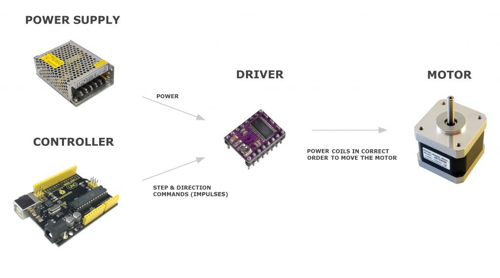
So- what we need to get these motors going? Let’s break it down to components and explain each part briefly. Commonly you need following parts to drive a stepper motor.

  1. Driver
  2. Microcontroller
  3. Power supply

I didn’t include a power supply for (micro)controller here since it’s self-explanatory. A microcontroller like in this case Arduino- gets its power from the USB cable or battery.

What do you need to get a stepper motor running?

Stepper Motor Driver
As we know- stepping motor can be moved one step at a time by applying electricity to coils in the correct order (and polarities). You could do this manually with some switches– step by step, but it has no practical use other than learning. This is where the driver comes into play.

The driver is doing the heavy lifting and it hides all the complexity behind a simple interface. It makes correct windings to be excited in the correct way based on the input signals. They usually have only 2 input pins which take commands in form of digital high and low. One sets the direction of rotation and other is for step commands.

Steps are given as digital pulses. After each step (HIGH) there must be (LOW) input for a moment. So drive can detect when new step command is given. If there is are no pulses given- there will be no steps done by the drive and motor.

What do you need to get a stepper motor running?

Direction input pin can be LOW or HIGH all the time, while steps are made, depending on the direction needed. Direction does not need impulses.

Note: Some small unipolar stepper motors are driven via transistor arrays or chips like uln2003 and ln2004. There can be 4 control wires instead of 2 from the microcontroller. In that configuration, the microcontroller is directly telling which wires (coils) to energize by turning correct ones on each step “manually”. Look at example schema on the Arduino page.

Microcontroller
It’s possible to make motors move by touching the step pin on driver manually with HIGH wire. But that would not be very practical other than testing. This is why microcontroller comes into play. Microcontrollers can give many hundreds or even thousands of impulses per second so the motor can be rotated very fast and accurate.

Which has higher torque? nema 17 or nema 23?

How to choose the NEMA 23 or the NEMA 34 stepper motors?