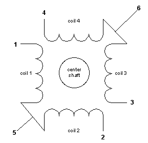
A stepper motor is a motor controlled by a series of electromagnetic coils. The center shaft has a series of magnets mounted on it, and the coils surrounding the shaft are alternately given current or not, creating magnetic fields which repulse or attract the magnets on the shaft, causing the motor to rotate. There are two basic types of stepper motors, unipolar steppers and bipolar steppers.
Unipolar Stepper Motors
The unipolar stepper motor for sale has five or six wires and four coils (actually two coils divided by center connections on each coil). The center connections of the coils are tied together and used as the power connection. They are called unipolar steppers because power always comes in on this one pole.
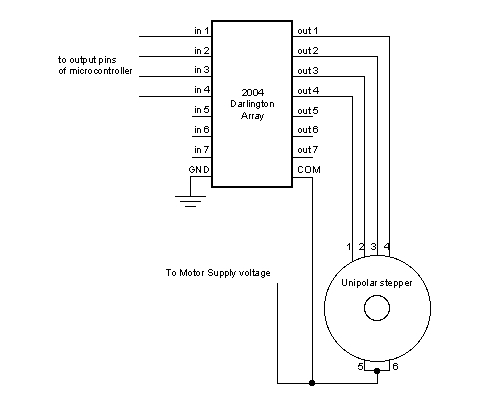
To control the stepper, apply voltage to each of the coils in a specific sequence. The sequence would go like this:
Bipolar stepper motors
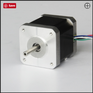
The bipolar stepper motor for sale usually has four wires coming out of it. Unlike unipolar steppers, bipolar steppers have no common center connection. They have two independent sets of coils instead. You can distinguish them from unipolar steppers by measuring the resistance between the wires. You should find two pairs of wires with equal resistance. If you’ve got the leads of your meter connected to two wires that are not connected (i.e. not attached to the same coil), you should see infinite resistance (or no continuity). Like other motors, stepper motors require more power than a microcontroller can give them, so you’ll need a separate power supply for it. Ideally you’ll know the voltage from the manufacturer, but if not, get a variable DC power supply, apply the minimum voltage (hopefully 3V or so), apply voltage across two wires of a coil (e.g. 1 to 2 or 3 to 4) and slowly raise the voltage until the motor is difficult to turn. It is possible to damage a motor this way, so don’t go too far.
To control a bipolar stepper motor, you give the coils current using to the same steps as for a unipolar stepper motor. However, instead of using four coils, you use the both poles of the two coils, and reverse the polarity of the current.
So for examples, if you have a 1.8-degree stepper, and it’s turned 200 steps, then it’s turned 1.8 x 200 degrees, or 360 degrees, or one full revolution. In every step of the sequence, two wires are always set to opposite polarities. Because of this, it’s possible to control steppers with only two wires instead of four, with a slightly more complex circuit. The stepping sequence is the same as it is for the two middle wires.

 The
The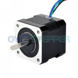
 5A 86x86x150mm")
