Posted on Leave a comment

Advantages and disadvantages of the PM Stepper Motor

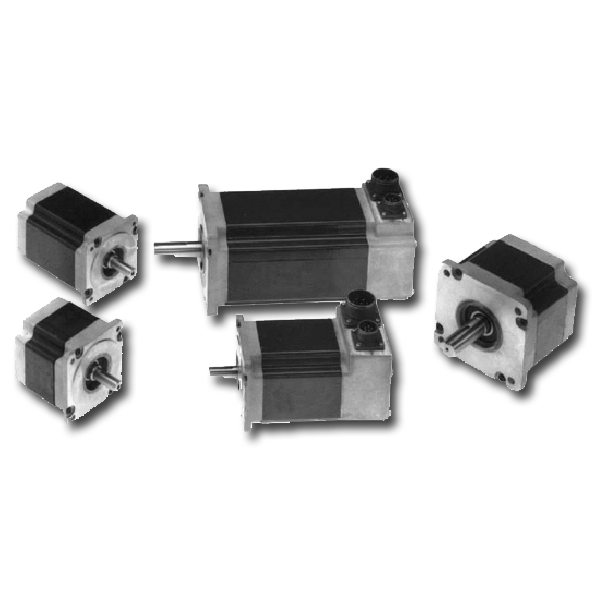
What is a Permanent magnet stepper motor?

Permanent magnet stepper motors are rotated using a magnetic core that interacts with the stator’s pulsed electromagnetic field.

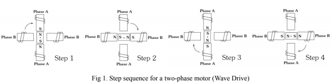
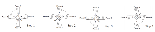
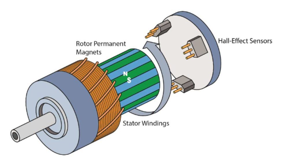
Two-phase permanent magnet step motors are usually two-phase. They have small torque and volume and a stepping angle of 7.5 to 15 degrees. There are two parts to a motor: the stator and the rotor. If the stator has a coil, then the rotor will be a permanent magnetic magnet. Or, the stator can be a coil and the rotor a coil.

Principle of the Stepper Motor

The principle of operation of the stepper motor works in a similar way to a conventional motor. It operates on the principle known as Lorentz Force law. It states that a current-carrying conductor placed in a magnetic field experiences a force due to the interaction between fluxes.

There are two types of flux that interact: stator magnetic flux (or rotor magnet flux). External excitations create the stator magnetic flux, while permanent magnets create the rotor. Fleming’s left hand rule governs the direction of motor.

Advantages and disadvantages of the Stepper Motor

Permanent magnet stepper motors offer many benefits.

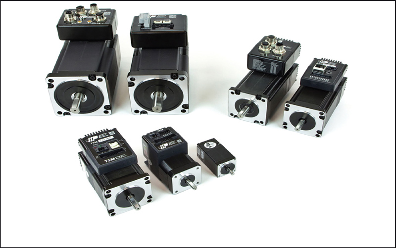
Its compact size makes it ideal for many applications.

The losses are lower because there is no external excitation

The maintenance is lower because there is no external excitation.

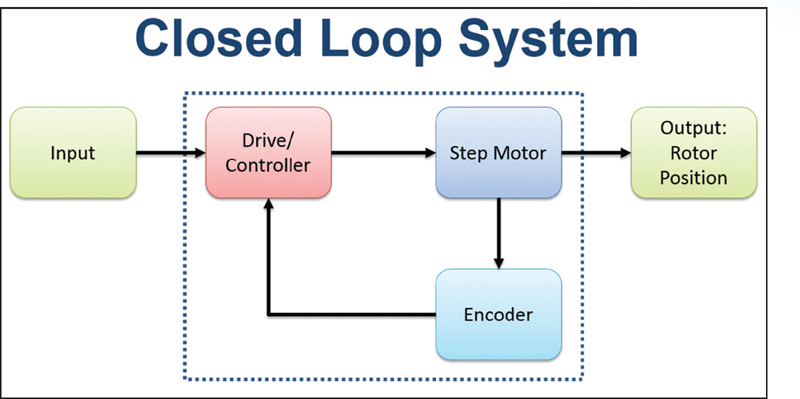
It can be connected with the external circuit to control the speed.

To locate the rotor windings, sensors may be used

It can be used in a wide range speed and torque.

Precise Control

A permanent magnet stepper motor has its disadvantages.

It cannot be used in high-power applications due to its limitations as a permanent magnet

The amount of torque produced is very limited

Permanent magnets have a limited life span.

Applications

Permanent magnet stepper motors have many applications.

Aeronautical industry

Robotics

Toys

Manufacturing

Control industry

Printing and mills

We have now seen the working principle, constructional details, and the applications of the pm stepper motor. It is important to note which magnetic materials can be used to increase the motor’s performance and how to control its step angle.

Posted on Leave a comment

Fundamentals of operation of stepper motor

A step motor for sale is an electric motor that rotates in discrete step increments. The movement of each step is precise and repeatable; therefore the motor’s position can be controlled precisely without any feedback mechanism, as long as the motor is carefully sized to the application.Industrial applications include high speed pick and place equipment and multi-axis CNC machines, often directly driving lead screws or ballscrews. In the field of optics they are frequently used in precision positioning equipment such as linear actuators, linear stages, rotation stages, goniometers, and mirror mounts. Other uses arein packaging machinery, and positioning of valve pilot stages for fluid control systems. Commercially, stepper motors are used in floppy disk drives, flatbed scanners, computer printers, plotters, slot machines, image scanners, compact disc drives and many more devices.

33

Energizing a coil winding creates an electromagnetic field with a north and south pole. The magnetic field created by the winding will cause the magnetized rotor to align itself with the magnetic field, since unlike poles attract.The direction of the magnetic field can be altered to create rotation of the rotor.

Fig 1. illustrates a typical step sequence for a two phase motor. In Step 1, phase A is energized; it locks the rotor in the position shown. In Step 2, phase A is turned off and phase B is turned on, the rotor rotates 90°clockwise. In Step 3, phase A is turned on again but with reversed polarity and in Step 4, phase B is turned on with reversed polarity. This sequence completes a full turn of the rotor. Repeating this sequence causes the rotor to rotate clockwise in 90° steps. This is the basic “one phase on” stepping.

Fundamentals of operation of stepper motor

Fig 2. Shows a more common “two phases stepping motor “where both phases are always energized.The rotor in this stepping mechanism alighs itself between the poles. This stepping method gives 41.4% more torque than “one phase on” stepping but requires twice the input power.

Fundamentals of operation of stepper motor

Posted on Leave a comment

How to Solve The Problem Of Stepping Motor Positioning?

Generally, the driving direction and pulse signal of the cheap stepping motor have certain requirements. For example, the driving direction of the rising or falling direction of the first pulse signal is different before the recognition of a few microseconds, otherwise there will be a pulse operation angle and rotation instead of the actual Need, the final failure phenomenon is the wider the walk, the more obvious the subdivision, the solution is mainly to use software to change the logic of hair, pulse or delay.

Since the characteristics of the stepper servo motor determine that the initial speed cannot be too high, especially in the case of a large load inertia, it is recommended that the initial speed be lower than 1 r / s. In this case, the impact is small and the system is subject to too much acceleration, which is easily overshooted, resulting in inaccurate positioning. There should be a certain pause between the forward and reverse rotation of the motor. Otherwise, the overshoot will be caused by an excessive reverse acceleration.

Image result for 23HS45-4204S
23HS45-4204S
  1. Adjust the value of the compensation parameter according to the actual situation. Since the elastic deformation of the timing belt is large, some compensation should be added when changing the direction.
  2. Appropriately increase the motor current and increase the drive voltage. Select a motor with a higher torque.
  3. System interference causes the controller or driver to malfunction, so we can only find the source of interference, reduce its interference ability, cut off the transmission path, and improve its anti-interference ability.

Common measures:

A. Replace the ordinary wire with a double shielded wire. The signal lines in the system are respectively connected to high current or high voltage conversion lines to reduce electromagnetic interference.

B. Use a power filter to filter out interference waves from the grid and add a line filter at the input of the main power-consuming device to reduce interference between devices in the system when conditions permit.

C. It is preferred to transmit signals between devices through an opto-isolator. Where permitted, the pulse and direction signals are preferably transmitted differentially by optical isolation. By adding a resistor-capacitor absorption or fast-release circuit at both ends, the inductive load can generate 10-100 times the peak voltage at the beginning of the inductive load.

https://mytrendingstories.com/member/jeffery-alan/
https://www.global-gathering.com/opinions/706

Posted on Leave a comment

Tips on Decreasing Noise on Your Stepper Driver

That stepper driver’s high pitch squealing is driving me nuts! Well, it has to drive you somehow as after all it is a “driver”, right? Well, nuts should not be it. It should drive your stepper motor and be done with it. But what if by nature stepper motors are noise and it is just a matter of learning to live with it?

Tips on Decreasing Noise on Your Stepper Driver
23HS22-1006S

Chances are you are not about to buy into such a lifestyle. You have heard quiet stepper drives and you want one to! So if you are experiencing some undesirable high pitch squealing from your stepper motor driver and are in need of reducing this horrendous form of ear-torture, feel free to check out these easy steps:

The SOURCE!
Where does it come from? Why can I hear it? Shouldn’t this motor be completely silent? If it were disabled it would be silent. But when energized, it is just not possible. Especially when we are regulating the winding currents by chopping them into submission. Current chopping is the preferred method of driving steppers nowadays. It is way much more efficient than having a humonghous resistor to limit the current, occupies less space, cost less and generates less heat. It is just the way to go.

Solution #1: Increase Switching Frequency
The current chopper circuitry will most likely offer you some way in which you can increase the switching frequency. For example, in the DRV8811 this is achieved by changing the R and C components at the RCx pins. These two components will change the TIME_OFF portion of the current regulation period. The smaller the TIME_OFF, the smaller the total current regulation period which is the same as the higher the frequency. Hence, you will want to decrease the R component to some value in which your frequency is considerably higher than 20 KHz.

Solution #2: Decrease Stepper Current
Decreasing the winding current also decreases the audible noise to some extent. This venue will work for both during run time as well as holding torque instances. During run time, the less current you use, the less vibration. However, it also means the less torque. So decreasing current will work up to some point. If you decrease too much, you may start loosing steps and this is a big NO NO when it comes to stepper driving. Since you are operating the motor in open loop, you must ensure the right amount of current is supplied at all times.

Solution #3: Use Slow Decay Versus Fast or Mixed Decay
When possible, you will want to operate your motor on slow decay current recirculation mode, instead of fast or mixed decay. This is especially true if you are actuating your motor with full step commutation. Other than decreased noise, as the current ripple is the smallest possible, you will also obtain the most efficient usage of your H Bridge. For example, under slow decay you will get better torque response due to the fact that average current is larger with this mode than with the higher current ripple observed while on fast decay mode.

SEE MORE: https://www.steppernews.com

Posted on Leave a comment

Size and NEMA standard of Stepper Motor You Should Consider

You will constantly be hearing about NEMA16, NEMA23
NEMA is the acronym for National Electrical Manufacturers Association.
When it says national, it really means USA. It is quite a paradox that every NEMA you buy uses the ‘national’ standard, but they are Made in China.
The number will indicate the size of the motor. To be more precise it will specify the front face, where the screws are located. NEMA17 means it’s dimensions will be 1.7×1.7 inches.

What types of stepper motors are available to buy ?
17hm08-1204s

It’s implied that usually the bigger the more torque will provide. Although it doesn’t have to be like that. It is totally feasible for a NEMA14 to over-match a NEMA17. It depends on the manufacturer and the specs of the motor design.
If the motor will be in a dynamic part of the machine, like the head or an extruder, then the size will really matter. The bigger the more weight, that will generate more momentum.

The NEMA14 are very light, but they are difficult to obtain with the necessary torque. The NEMA17 are the easiest to find and the most common ones for Arduino projects.

Which motor to buy?
Álvaro Rey, from MakerGal: If you are in doubt about which NEMA17 to choose, always buy the biggest. If you are afraid of not having enough torque get one of big 70oz.


Heat
Bear in mind that motors tend to get into quite a temperature. If they work at top of their specs, it is not uncommon for them to get to 80º degree Celsius. And if you happen to use PLA plastic for your machine…
You might end in big trouble!

Resistance
One of the motor characteristics is the internal resistance. How this influence us?
On one side it is the heat released. Due having more resistance, the motor will heat more.

Voltage
This value also generates lots of confusion. It is very common for the motor to have a value like 3.6V, but we obviously have a 12V power supply. What can we do?

Motor Voltage and the power supply
It totally different the maximum motor voltage than the driver voltage.

Shaft Type:
It is important to check the shaft diameter and the length.
Make sure you are going to use the gears correctly and to secure the setscrews firmly.
Also, make sure the gear will fit in the motor and the shaft to not be too long.
I am quite pedantic over it since it is not the first time I suffered that problem, or that i have to short the length of a shaft.

Shaft types
There are 3 types
Round shaft. The most common one.
Flatted section shaft. It is round but it has a flat section. Therefore we can use them with a setscrew easily.
Threaded shaft. Since it is also very common to attach a threaded shaft to the motor, there are motors which already come with a threaded shaft installed to be used with a nut. It is even possible to order them to specs.

NEMA17 Motors For Modern 3D Printers

How to deduce stepping motor wiring?

Posted on Leave a comment

Medical Applications of Brushless dc Motor

Brushless-dc motors are taking center stage in medical-equipment design because they last twice as long a competing technologies.

It used to be that brushless-dc (BLDC) motors just weren’t an option for most medical applications. But that situation is changing as the cost of BLDC drive electronics falls. Furthermore, a quest for more-efficient, compact, and reliable medical equipment has put BLDC motors on the prescription list for a variety of applications.

Treating sleep apnea
The treatment of sleep apnea requires the use of Positive Airway Pressure (PAP) respirators. The patient dons a special breathing mask attached to the PAP respirator. A blower fan within the respirator pressurizes the air in the mask to create positive airway pressure that helps the patient breathe while asleep. The blower fan must raise or lower the patient’s airway pressure in response to their breathing pattern.

Power density and reliability
There’s no question that recent events have put a strain on the world’s medical analysis and testing services. Reason’s include the continuing development and improvement of medical technologies in the areas of disease detection, prevention, and treatment. Moreover, there’s been a double-digit increase in the number of people needing medical care over the last decade. The growing worldwide demand for medical analysis and testing services has created a niche for equipment with greater throughput and high reliability.

Medical analyzers
Medical analyzers are multifunction machines that test human bodily fluids such as blood and urine. Fluid samples within the analyzers move from station to station for various tests. Generally, medical analyzers are totally enclosed. The temperature within them will rise to well above ambient temperature during periods of peak operation. Medical analyzers are designed to test thousands of samples annually and to run a minimum of 8 hr daily.

All in all, a need for high throughput and reliability in medical machines will continue to challenge the capabilities of brushed-dc motors. In addition, the trend toward squeezing more equipment functions into less volume promotes the use of smaller motors able to dissipate heat in small spaces. BLDC motors can meet these demands now and should continue to do so into the future.

https://stepper01.exblog.jp/239753527/
http://www.bloghotel.org/ccSTEPPER/527722/

Posted on Leave a comment

How to Select a Linear Stepper Motor Actuator

Stroke Length

In determining the right stepper motor linear actuator for a specific application it is necessary to understand stroke length. The stroke length allows the device to handle short or long operational distances. Most, but not all, stepper actuators have a stroke length that allows the actuator to move a specific amount. For example, a small actuator could move a curtain for a window, while a large actuator could move a curtain for a movie screen. As a result, a longer stroke length will increase the price of a linear actuator. Extra length is rarely required, so users should select stepper actuators that exactly fit the application.

Duty Cycle

Understanding the duty cycle, the elapsed time between operations, will provide a reasonable approximation of the expected lifetime of a stepper actuator. The duty cycle can be based on units of hours per day, minutes per hour, or strokes per minute. By managing the duty cycle one can increase the lifetime and the necessary maintenance required for the stepper actuator.

Load

One of the criteria for selecting a stepper actuator is to identify the amount of force required of the application. Defining the load required for the application can help identify the proper size and capabilities of the stepper actuator. The orientation also plays a key role in selecting the proper stepper actuator.


IMPORTANT NOTE: With a stepper actuator in a horizontal position, the overall load capabilities must compensate for the frictional force. With a stepper actuator in a vertical position, the load necessary is that of the weight due to the gravitational force.

Power Factor

Mechanical Power: The necessary requirement in calculating mechanical power is based on the linear force required to move the load multiplied by the speed at which the load will be moved.

Electrical Power: The electrical power is obtained through performance graphs illustrating force vs. speed and force vs. current, both of which are good representations of the performance of a stepper linear actuator. The performance graphs are specific to each specific stepper actuator model.

Hot:economy planetary gearbox, spur gearbox stepper motor

http://oyostepper1234.searchgi.com
https://oyostepper.webstarts.com/

Posted on Leave a comment

Application of Stepper Motors in Medical Electronics

1. Introduction
Currently, major therapeutic methods in the treatment of open, complicated and unstable fractures in traumatology, orthopaedics and surgery (limbs, joints, the pelvis, jaws, etc.) include external fixators. This therapeutic method provides the advantage of simple application of the external fixator with perfect stabilisation of the fracture,allowing for timely rehabilitation of the patient. External fixators can also be used to extend limbs or to correct axial deformities. However, no fixator has been made until now that would provide motor control of joint movement – advisable and desired for therapy associated with rehabilitation in unconscious patients or patients with complicated joint fractures. VSB-TU Ostrava has gained practical experience in this field in cooperation with University Hospital in Ostrava; fixator prototypes which are equipped with an electric stepper motor to control joint bending in patients exist.There are currently two solution variants that can be considered for the electric actuation, in principle.

Application of Stepper Motors in Medical Electronics

1.1 Hybrid Actuators with Stepper Motors
Hybrid linear actuator stepper motor transfer the rotation movement of the stepper to the movement of a linear screw with the help of a special patented nut. The actuator contains a hybrid stepper motor, which utilizes both the advantages of a reluctance motor and a motor with permanent magnets. The construction is based on a reluctance motor and ensures a small step angle (up to 0.9°) and fine resolution. The use of permanent magnets on the other hand increases the turning moment and provides a stronger motor. The composition of these two technologies together with the movement nut into a single case creates an affordable compact linear drive  a hybrid stepper actuator.

Hybrid actuators represent an affordable solution for all application requiring small and exact control of a linear movement. Actuators create large forces in small spaces.The actuator contains a standard stepper motor, which may be simply controlled in the same way as stepper motors. The core of the hybrid actuator is an exact trapezoidal movement screw and nut shaped for the corresponding load. Integration of the movement screw in the motor provides a compact and precise drive unit which simplifies the construction of the resulting machine. Actuators find applications in medicine, measuring technology, handling technology and in other areas.

1.2 Stepper Motor Combined with a Linear Lead
The other possibility is offered by using a linear lead in connection with a standard two-phase stepper motor. The Kuroda linear lead used to convert rotational linearmovement can be mentioned as an example.The lead is equipped with a ball screw for positioning medium- up to heavy-weight
loads. The lead converts rotational movement of the stepper motor to the linear movement of the positioned load. An optimum configuration of the linear drive is obtained by combining the stepper motor and linear lead.

Which is Better for Cnc? Servo or Stepper Motors?

Torque and Speed Considerations Of Stepper Motor
Posted on Leave a comment

Advantages, Applications & Control of Brushless DC Motor

A brushless DC motor consists of a rotor in form of a permanent magnet and stator in form of polyphase armature windings. It differs from conventional dc motor in such that it doesn’t contains brushes and the commutation is done using electrically, using a electronic drive to feed the stator windings.

Advantages, Applications & Control of Brushless DC Motor

4 Pole 2 Phase Motor Operation
The brushless DC motor is driven by an electronic drive which switches the supply voltage between the stator windings as the rotor turns. The rotor position is monitored by the transducer (optical or magnetic) which supplies information to the electronic controller and based on this position, the stator winding to be energized is determined. This electronic drive consists of transistors (2 for each phase) which are operated via a microprocessor.

7 Advantages of Brushless DC Motors
Better speed versus torque characteristics
High dynamic response
High efficiency
Long operating life due to a lack of electrical and friction losses
Noiseless operation
Higher speed ranges

Applications:
The cost of the Brushless DC Motor for sale has declined since its presentation, because of progressions in materials and design. This decrease in cost, coupled with the numerous focal points it has over the Brush DC Motor, makes the Brushless DC Motor a popular component in numerous distinctive applications. Applications that use the BLDC Motor include, yet are not constrained to:

Consumer electronics
Transport
Heating and ventilation
Industrial engineering
Model engineering
Principle of Working


The principles for the working of a BLDC motors are the same as for a brushed DC motor, i.e., the internal shaft position feedback. In case of a brushed DC motor, feedback is implemented using a mechanical commutator and brushes. Within BLDC motor, it is achieved using multiple feedback sensors. In BLDC motors we mostly use Hall-effect sensor, whenever rotor magnetic poles pass near the hall sensor, they generate a HIGH or LOW level signal, which can be used to determine the position of the shaft. If the direction of the magnetic field is reversed, the voltage developed will reverse too.

What are Brushless DC Motors Used For?

Brush DC Motor VS Brushless DC Motor

Posted on Leave a comment

How to Improve Step Motor Performance with Encoder

Step motors are widely used in automation due to their high resolution, precision positioning, minimal control electronics, and low cost. As an open loop system, traditional step motors are driven without the need for sensors to feed information back to a controller; however, the open loop configuration of step motors has challenges.

ENCODER FUNCTIONALITIES
Figure 1.< By adding an inexpensive encoder to a step motor system, the drive/controller can monitor the motor’s actual position, closing the feedback loop and avoiding many of the limitations traditionally associated with stepper systems.

How to Improve Step Motor Performance with Encoder

The addition of an stepper motor encoder to the step motor system (Figure 1) adds functionality to detect and even prevent stalls by providing feedback to the drive. Depending upon how an operator programs the controller, encoder feedback can verify motor position, immediately detect motor stall, prevent motor stall, and create a closed loop servo system.

Position Verification — When pushed beyond its limits, a step motor will stall before reaching the endpoint. This event typically occurs when motors are not adequately specified for high-cycle applications. An encoder can provide position feedback at the end of the motion profile, indicating if the step motor stopped before reaching the end position

Stall Detection — Stall detection notifies the user/system/machine as soon as a motor stall occurs, eliminating the uncertainty of whether or not the motor reached its target position. A more advanced function than position verification, stall detection (Figure 2) enables the controller to compare the registers of the encoder counts and target motor position on a continuous basis instead of just at the end of the move.

Stall Prevention— While greatly increasing system functionality, stall detection does not inherently improve step motor performance; it still requires the operator to perform a corrective move and re-reference the axis to the home position. Stall prevention, on the other hand, dynamically and automatically adjusts the move profile to prevent a stall, enabling the motor to operate with constant torque to get into an accurate end position without stalling.

Servo Control and Increased Motor Torque — Using encoder feedback to servo-control, a step motor increases motor torque for greater dynamic performance. With peak torques up to 50% higher than the rated holding torque of the motor, the servo-controlled step motor system can operate at higher acceleration rates and with higher throughput for faster machine cycles.

How to Improve Step Motor Performance with Encoder

When working as part of a fully closed loop stepper motor system, step motors run cooler, more efficiently, quieter, and with faster settling times than their open loop counterparts. Unlike the other encoder applications described here, servo control applies a peak torque that enables the motor to get past stall conditions without sacrificing speed. Some manufacturers offer motors (Figure 3) already preconfigured with a high-resolution incremental encoder and closed-loop servo control firmware.

https://blog.oyostepper.com/2019/12/13/what-is-a-stepper-motor/