Posted on Leave a comment

Fundamentals of operation of stepper motor

A step motor for sale is an electric motor that rotates in discrete step increments. The movement of each step is precise and repeatable; therefore the motor’s position can be controlled precisely without any feedback mechanism, as long as the motor is carefully sized to the application.Industrial applications include high speed pick and place equipment and multi-axis CNC machines, often directly driving lead screws or ballscrews. In the field of optics they are frequently used in precision positioning equipment such as linear actuators, linear stages, rotation stages, goniometers, and mirror mounts. Other uses arein packaging machinery, and positioning of valve pilot stages for fluid control systems. Commercially, stepper motors are used in floppy disk drives, flatbed scanners, computer printers, plotters, slot machines, image scanners, compact disc drives and many more devices.

33

Energizing a coil winding creates an electromagnetic field with a north and south pole. The magnetic field created by the winding will cause the magnetized rotor to align itself with the magnetic field, since unlike poles attract.The direction of the magnetic field can be altered to create rotation of the rotor.

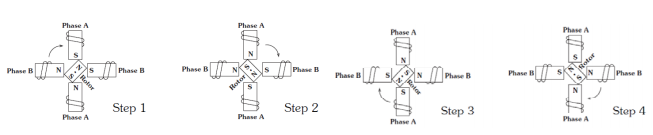
Fig 1. illustrates a typical step sequence for a two phase motor. In Step 1, phase A is energized; it locks the rotor in the position shown. In Step 2, phase A is turned off and phase B is turned on, the rotor rotates 90°clockwise. In Step 3, phase A is turned on again but with reversed polarity and in Step 4, phase B is turned on with reversed polarity. This sequence completes a full turn of the rotor. Repeating this sequence causes the rotor to rotate clockwise in 90° steps. This is the basic “one phase on” stepping.

Fundamentals of operation of stepper motor

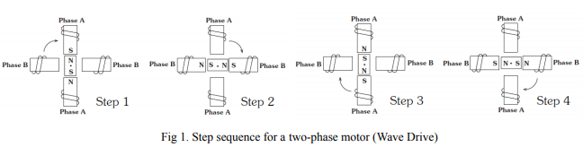
Fig 2. Shows a more common “two phases stepping motor “where both phases are always energized.The rotor in this stepping mechanism alighs itself between the poles. This stepping method gives 41.4% more torque than “one phase on” stepping but requires twice the input power.

Fundamentals of operation of stepper motor

Posted on Leave a comment

How to Solve The Problem Of Stepping Motor Positioning?

Generally, the driving direction and pulse signal of the cheap stepping motor have certain requirements. For example, the driving direction of the rising or falling direction of the first pulse signal is different before the recognition of a few microseconds, otherwise there will be a pulse operation angle and rotation instead of the actual Need, the final failure phenomenon is the wider the walk, the more obvious the subdivision, the solution is mainly to use software to change the logic of hair, pulse or delay.

Since the characteristics of the stepper servo motor determine that the initial speed cannot be too high, especially in the case of a large load inertia, it is recommended that the initial speed be lower than 1 r / s. In this case, the impact is small and the system is subject to too much acceleration, which is easily overshooted, resulting in inaccurate positioning. There should be a certain pause between the forward and reverse rotation of the motor. Otherwise, the overshoot will be caused by an excessive reverse acceleration.

Image result for 23HS45-4204S
23HS45-4204S
  1. Adjust the value of the compensation parameter according to the actual situation. Since the elastic deformation of the timing belt is large, some compensation should be added when changing the direction.
  2. Appropriately increase the motor current and increase the drive voltage. Select a motor with a higher torque.
  3. System interference causes the controller or driver to malfunction, so we can only find the source of interference, reduce its interference ability, cut off the transmission path, and improve its anti-interference ability.

Common measures:

A. Replace the ordinary wire with a double shielded wire. The signal lines in the system are respectively connected to high current or high voltage conversion lines to reduce electromagnetic interference.

B. Use a power filter to filter out interference waves from the grid and add a line filter at the input of the main power-consuming device to reduce interference between devices in the system when conditions permit.

C. It is preferred to transmit signals between devices through an opto-isolator. Where permitted, the pulse and direction signals are preferably transmitted differentially by optical isolation. By adding a resistor-capacitor absorption or fast-release circuit at both ends, the inductive load can generate 10-100 times the peak voltage at the beginning of the inductive load.

https://mytrendingstories.com/member/jeffery-alan/
https://www.global-gathering.com/opinions/706

Posted on Leave a comment

Tips on Decreasing Noise on Your Stepper Driver

That stepper driver’s high pitch squealing is driving me nuts! Well, it has to drive you somehow as after all it is a “driver”, right? Well, nuts should not be it. It should drive your stepper motor and be done with it. But what if by nature stepper motors are noise and it is just a matter of learning to live with it?

Tips on Decreasing Noise on Your Stepper Driver
23HS22-1006S

Chances are you are not about to buy into such a lifestyle. You have heard quiet stepper drives and you want one to! So if you are experiencing some undesirable high pitch squealing from your stepper motor driver and are in need of reducing this horrendous form of ear-torture, feel free to check out these easy steps:

The SOURCE!
Where does it come from? Why can I hear it? Shouldn’t this motor be completely silent? If it were disabled it would be silent. But when energized, it is just not possible. Especially when we are regulating the winding currents by chopping them into submission. Current chopping is the preferred method of driving steppers nowadays. It is way much more efficient than having a humonghous resistor to limit the current, occupies less space, cost less and generates less heat. It is just the way to go.

Solution #1: Increase Switching Frequency
The current chopper circuitry will most likely offer you some way in which you can increase the switching frequency. For example, in the DRV8811 this is achieved by changing the R and C components at the RCx pins. These two components will change the TIME_OFF portion of the current regulation period. The smaller the TIME_OFF, the smaller the total current regulation period which is the same as the higher the frequency. Hence, you will want to decrease the R component to some value in which your frequency is considerably higher than 20 KHz.

Solution #2: Decrease Stepper Current
Decreasing the winding current also decreases the audible noise to some extent. This venue will work for both during run time as well as holding torque instances. During run time, the less current you use, the less vibration. However, it also means the less torque. So decreasing current will work up to some point. If you decrease too much, you may start loosing steps and this is a big NO NO when it comes to stepper driving. Since you are operating the motor in open loop, you must ensure the right amount of current is supplied at all times.

Solution #3: Use Slow Decay Versus Fast or Mixed Decay
When possible, you will want to operate your motor on slow decay current recirculation mode, instead of fast or mixed decay. This is especially true if you are actuating your motor with full step commutation. Other than decreased noise, as the current ripple is the smallest possible, you will also obtain the most efficient usage of your H Bridge. For example, under slow decay you will get better torque response due to the fact that average current is larger with this mode than with the higher current ripple observed while on fast decay mode.

SEE MORE: https://www.steppernews.com

Posted on Leave a comment

Size and NEMA standard of Stepper Motor You Should Consider

You will constantly be hearing about NEMA16, NEMA23
NEMA is the acronym for National Electrical Manufacturers Association.
When it says national, it really means USA. It is quite a paradox that every NEMA you buy uses the ‘national’ standard, but they are Made in China.
The number will indicate the size of the motor. To be more precise it will specify the front face, where the screws are located. NEMA17 means it’s dimensions will be 1.7×1.7 inches.

What types of stepper motors are available to buy ?
17hm08-1204s

It’s implied that usually the bigger the more torque will provide. Although it doesn’t have to be like that. It is totally feasible for a NEMA14 to over-match a NEMA17. It depends on the manufacturer and the specs of the motor design.
If the motor will be in a dynamic part of the machine, like the head or an extruder, then the size will really matter. The bigger the more weight, that will generate more momentum.

The NEMA14 are very light, but they are difficult to obtain with the necessary torque. The NEMA17 are the easiest to find and the most common ones for Arduino projects.

Which motor to buy?
Álvaro Rey, from MakerGal: If you are in doubt about which NEMA17 to choose, always buy the biggest. If you are afraid of not having enough torque get one of big 70oz.


Heat
Bear in mind that motors tend to get into quite a temperature. If they work at top of their specs, it is not uncommon for them to get to 80º degree Celsius. And if you happen to use PLA plastic for your machine…
You might end in big trouble!

Resistance
One of the motor characteristics is the internal resistance. How this influence us?
On one side it is the heat released. Due having more resistance, the motor will heat more.

Voltage
This value also generates lots of confusion. It is very common for the motor to have a value like 3.6V, but we obviously have a 12V power supply. What can we do?

Motor Voltage and the power supply
It totally different the maximum motor voltage than the driver voltage.

Shaft Type:
It is important to check the shaft diameter and the length.
Make sure you are going to use the gears correctly and to secure the setscrews firmly.
Also, make sure the gear will fit in the motor and the shaft to not be too long.
I am quite pedantic over it since it is not the first time I suffered that problem, or that i have to short the length of a shaft.

Shaft types
There are 3 types
Round shaft. The most common one.
Flatted section shaft. It is round but it has a flat section. Therefore we can use them with a setscrew easily.
Threaded shaft. Since it is also very common to attach a threaded shaft to the motor, there are motors which already come with a threaded shaft installed to be used with a nut. It is even possible to order them to specs.

NEMA17 Motors For Modern 3D Printers

How to deduce stepping motor wiring?