Posted on Leave a comment

Stepper Motor Control by Varying Clock Pulses

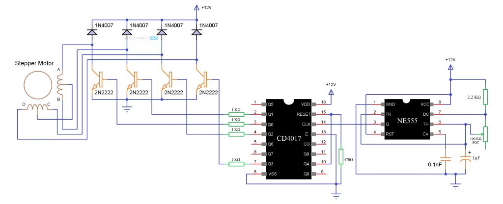
Stepper motor control circuit is a simple and low-cost circuit, mainly used in low power applications. The circuit is shown in figure, which consist 555 timers IC as stable multi-vibrator. The frequency is calculated by using below given relationship:
Stepper Motor Control by Varying Clock Pulses

Frequency = 1/T = 1.45/(RA + 2RB)C Where RA = RB = R2 = R3 = 4.7 kilo-ohm and C = C2 = 100 µF.

The output of timer is used as clock for two 7474 dual ‘D’ flip-flops (U4 and U3) configured as a ring counter. When power is initially switched on, only the first flip-flop is set (i.e. Q output at pin 5 of U3 will be at logic ‘1’) and the other three flip-flops are reset (i.e. output of Q is at logic 0). On receipt of a clock pulse, the logic ‘1’ output of the first flip-flop gets shifted to the second flip-flop (pin 9 of U3). Thus logic 1 output keeps shifting in a circular manner with every clock pulse. Q outputs of all the four flip-flops are amplified by Darling-ton transistor arrays inside ULN2003 (U2) and connected to the stepper motor windings orange ,brown, yellow, black to 16, 15 ,14, 13 of ULN2003 and the red to +ve supply.

The common point of the winding is connected to +12V DC supply, which is also connected to pin 9 of ULN2003. The color code used for the windings is may vary form make to make. When the power is switched on, the control signal connected to SET pin of the first flip-flop and CLR pins of the other three flip-flops goes active ‘low’ (because of the power-on-reset circuit formed by R1-C1 combination) to set the first flip-flop and reset the remaining three flip-flops. On reset, Q1 of IC3 goes ‘high’ while all other Q outputs go ‘low’. External reset can be activated by pressing the reset switch. By pressing the reset switch, you can stop the stepper motor. The motor again starts rotating in the same direction by releasing the reset switch.

Now you have got an idea about the types of super motors and its applications if you have any queries on this topic or on the electrical and electronic projects leave the comments below.

https://pro.ideafit.com/node/5240467
https://activerain.com/blogsview/5437527/how-to-choose-a-stepper-motor-and-power-supply-voltage
Posted on Leave a comment

How to Choose the Right Linear Actuator for Your CNC Project

Selecting the appropriate linear actuator can be quite the ordeal – and selecting the wrong one could dramatically reduce the efficiency of your application, and shorten its lifespan. Learn about the different types of linear actuators, how to select the right one, and which services can help make the decision as simple as 1-2-3!

There are few different designs of linear actuators you need to consider when selecting an actuator for your design; each design has its advantages and disadvantages, and serves unique purpose, so let’s examine each design:

The maximum force this application can handle is also limited, meaning that you should carefully consider how much strength you’ll need before selecting the external nut configuration.

External Nut
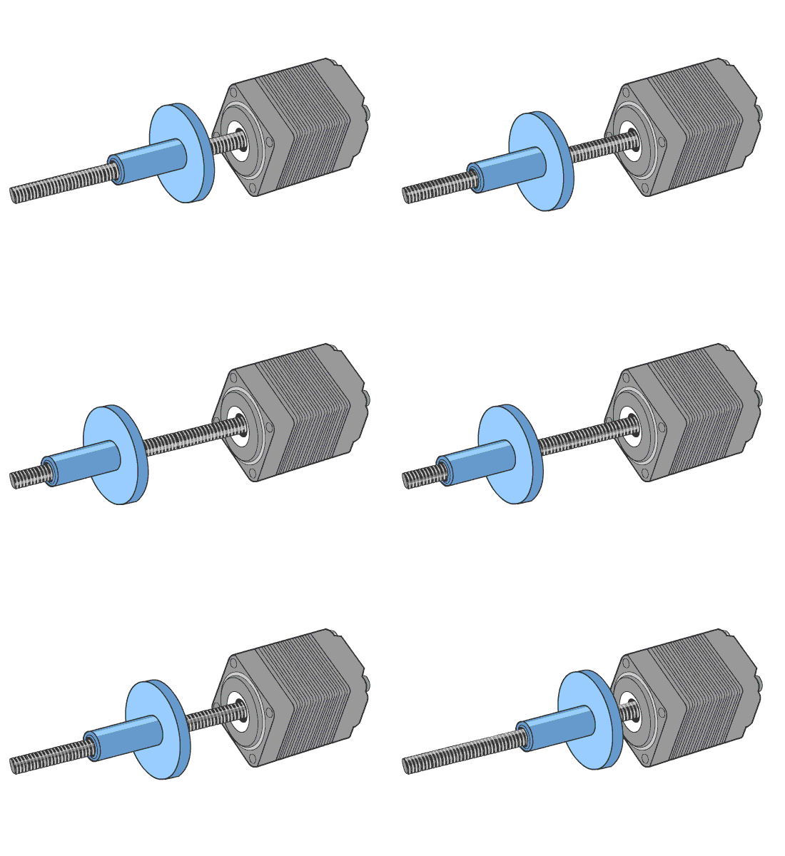
The most popular design of linear stepper actuators, the external nut configuration is simple, compact, and offers a high level of design flexibility. In the external nut configuration, the shaft of the stepper motor is replaced with a lead screw. In a typical application, the motor is fixed in position and an apparatus is attached to the nut. As the lead screw rotates, the external nut travels along the length of the screw, providing linear motion.

External Nut Stepper Motor

Non-Captive
In non-captive configuration, the nut is incorporated into the motor’s rotor. As the rotor rotates, it creates linear motion by passing the leadscrew through the shaft. In this instance, your apparatus can be attached in one of two ways: directly to the motor, or to the leadscrew.

Non-Captive Stepper Motor

The mass of the motor can also limit the acceleration and maximum operating speed of your application, and certain power efficiency is sacrificed because more mass needs to be moved.

Another popular option is to attach an apparatus to the lead screw while keeping the motor fixed in position. This removes the need for long leads and lead tracking. Most of the benefits can be retained if the apparatus can be supported from both ends of the lead screw.

Captive

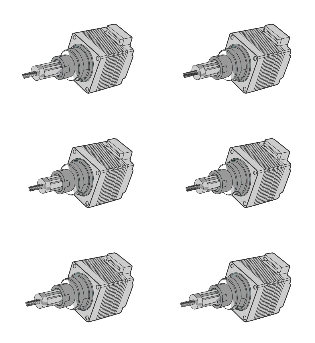
Captive Stepper Motor


The third common configuration is the captive linear actuator. In this design, a screw is attached to a splined shaft. That shaft is prevented from spinning through the use of a splined socket attached to the face of the motor. Linear motion is achieved while each component is rotationally fixed and where no rotation is visible from outside. This is a good choice if your application lacks a mechanism which prevents either the lead screw or the nut from rotating.