The decision between NEMA 23 and NEMA 34 motors is primarily a decision about productivity — NEMA 34 motors can remove material at a higher rate using higher feed rates and deeper cut depths. The style of motor you choose is not the determining factor in what materials can be cut — this is far more a function of the mechanical stiffness of the machine doing the cutting, as well as proper speeds, feeds and tooling. With our machine kits, either of our motor packages can cut hardwood, plastic, and non-ferrous materials such as aluminum.
Motors serve to accelerate and decelerate components of the machine (such as the gantry or z axis), as well as to push the cutting bit through material. NEMA 34 motors can take deeper passes through material and improve cutting speeds, especially on larger machines.
Generally, if you are using a machine for regular production work, higher power NEMA 34 motors will provide a fast return on investment. However, if you are primarily doing small production runs or prototyping work, NEMA 23 motors will likely be sufficient.
Every 3D printer has them, but what exactly are stepper drivers and what do they do? Read on to see what drives your 3D printer to create amazing models.
What are Stepper Drivers
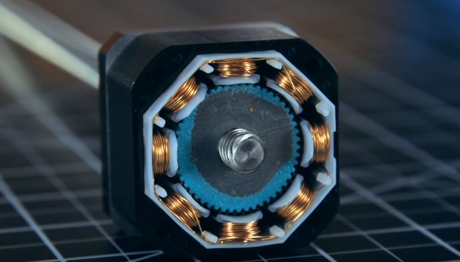
Under the hood of every 3D printer, 3D carver, or CNC, there are stepper drivers. They control and cause the coils in stepper motors to trigger, making the shaft of the motor rotate in a precisely controlled manner. Some control boards have the stepper drivers integrated as part of the board, and others have them as swappable and replaceable plug-ins. There’s an advantage and disadvantage to every form, so let’s take a look at what these little guys are capable of.
How they work: Digital Stepper drivers all have a central chip that processes inputs and outputs them as movements across each axis. Nema17 stepper motors have a certain number of steps per rotation (with most being 200) which is just how many changes in the magnetic field of the coil will it take to completely rotate the motor shaft. By carefully controlling the current that the driver outputs, it will magnetize one side of the motor, causing the shaft to spin, and by constantly and consistently changing which side is magnetized is how the motor spins.
What is microstepping:gearbox stepper motor Drivers can also do something called “microstepping” where instead of moving strictly one tooth of the gear or step at a time, the driver can apply just enough current to hold the gear between steps, increasing the accuracy of the output motion. As of today, 1/16th microstepping is fairly standard, and has been for a while, but there are some drivers that can go to 1/32, 1/64, 1/128, or even 1/256 microstepping. The more microstepping that a driver outputs, the more current it will need to be able to have the torque to hold those fine positions.
Stepper motors are inherently open-loop devices. They don’t require feedback because each pulse of current delivered by the drive equals one step of the motor (or a fraction of a step in the case of microstepping). Plus with small step sizes (or step angles) the motor’s position can be determined very precisely without the need for a feedback device and complicated control schemes.
So, if a stepper motor’s position can be determined in an open-loop system, why would you add the cost and complexity of closed-loop control to a stepper motor?
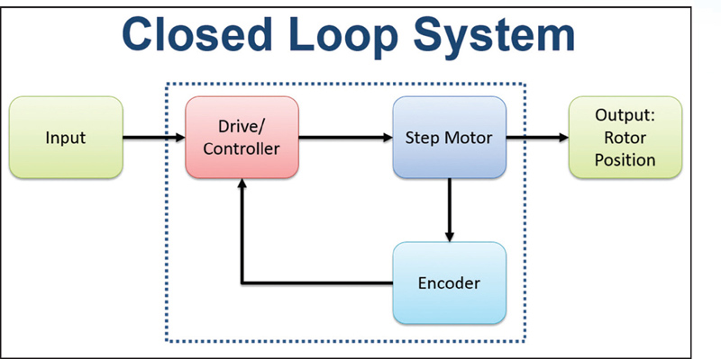
There are generally three types of closed-loop control for stepper motors, each offering a different level of positioning control and complexity.
Step-loss compensation: Reactive position correction at the end of the move
The most common type of closed-loop stepper system is based on step-loss compensation, also referred to as step-loss control or stepper position maintenance. In this setup, the drive operates in microstepping mode, and an encoder tracks the shaft (or load) position. If lost steps are detected, based on the commanded position (number of steps multiplied by step angle) versus the actual position read by the encoder, the controller commands additional steps so the motor (or load) reaches the desired position.
Load position control: Continuous, real-time position correction without complex controls
Load position control, also referred to as closed-loop microstepping, continuously monitors the shaft (or load) position and generates an error signal. The controller uses this error signal to adjust the commands in real-time, during the entire move profile.
Servo control: Complete control of torque and position
The most advanced closed-loop stepper control method is to operate the motor as a two-phase brushless (BLDC) motor. (Note that many stepper motors have two phases offset by 90° whereas brushless dc motors have three phases offset by 120°.) This method is referred to as servo stepper or closed-loop stepper control.
Stepper motor systems using closed-loop control represent a small percentage of stepper motor applications, but if loss of position could be catastrophic to the application, yet the system requires high torque at low speed, relatively simple architecture, and relatively low cost (compared to a true servo motor system) a closed-loop stepper might be the most appropriate solution.
Following chapter is a very high overview. Please read further down about more practical info about the drive and motor types. But basics presented here is pretty universal and widely used in DIY community.
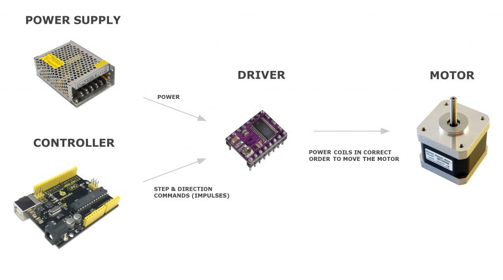
So- what we need to get these motors going? Let’s break it down to components and explain each part briefly. Commonly you need following parts to drive a stepper motor.
Driver
Microcontroller
Power supply
I didn’t include a power supply for (micro)controller here since it’s self-explanatory. A microcontroller like in this case Arduino- gets its power from the USB cable or battery.
Stepper Motor Driver As we know- stepping motor can be moved one step at a time by applying electricity to coils in the correct order (and polarities). You could do this manually with some switches– step by step, but it has no practical use other than learning. This is where the driver comes into play.
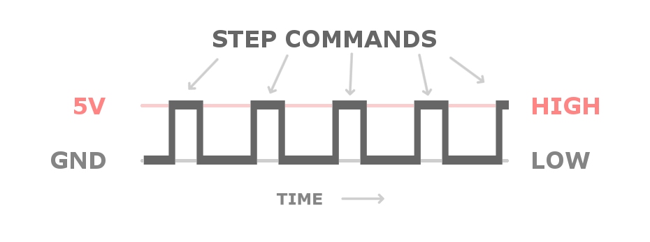
The driver is doing the heavy lifting and it hides all the complexity behind a simple interface. It makes correct windings to be excited in the correct way based on the input signals. They usually have only 2 input pins which take commands in form of digital high and low. One sets the direction of rotation and other is for step commands.
Steps are given as digital pulses. After each step (HIGH) there must be (LOW) input for a moment. So drive can detect when new step command is given. If there is are no pulses given- there will be no steps done by the drive and motor.
Direction input pin can be LOW or HIGH all the time, while steps are made, depending on the direction needed. Direction does not need impulses.
Note: Some small unipolar stepper motors are driven via transistor arrays or chips like uln2003 and ln2004. There can be 4 control wires instead of 2 from the microcontroller. In that configuration, the microcontroller is directly telling which wires (coils) to energize by turning correct ones on each step “manually”. Look at example schema on the Arduino page.
Microcontroller It’s possible to make motors move by touching the step pin on driver manually with HIGH wire. But that would not be very practical other than testing. This is why microcontroller comes into play. Microcontrollers can give many hundreds or even thousands of impulses per second so the motor can be rotated very fast and accurate.
Whilst looking a parts for a Kossel, a large Kossel (see Kossel 3D Printer), I came across these aluminium vertices for 2040 aluminium from RobotDigg, see 2040 or 3030 Alu Vertex for Kossel XXL or XXXL. On that product page they recommend using Nema 23, en lieu of Nema 17, stepper motors and, indeed, offer a vertex machined especially to take a Nema 23 stepper motor.
Now, Nema 17 stepper motors are pretty well covered in the RepRap forums, and there are three common favourites. However, the choice is not so clear for Nema 23 stepper motors. I decided to do some research on which Nema 23 stepper motors would be appropriate.
Links
Take a look at the RepRap Wiki page for Nema motors.
From Choosing stepper for a delta:
Using NEMA23 stepper motors for printers
For large machines, there are questions of the interest to use larger size steppers for movement or extruder, say Nema23 sized motors. However, Nema23 steppers are less optimised than Nema17 for micro-steps so there will be loss of precision. In addition, the rotating inertia is larger, so rapid change capacities may be reduced, driving to difficulties at corners. All steppers will have an increase of vibrations at medium step rates. This is called ‘mid-band resonance’. NEMA 23 steppers may be more prone to have this problem, at a lower frequency than NEMA 17 stepper motors. So, it is preferable to use long NEMA 17 stepper motors than NEMA23. Electrically, larger motors will need more current, whatever their size.
Nema 17 is most likely more than adequate, depending on your speeds. The bigger challenge is going to be a bowden system that isn’t 6 ft long… Perhaps a counter-weighted bowden floating head.
From Running NEMA 23 motors, again after RobotDigg’s recommendation:
…have been advised (by RobotDigg who make the frame corners) to consider NEMA 23 (76mm). These are rated at 6.7V 2.8A
2.8A is too high for the Duet. However, you can also get Nema 23 motors with 1.5A or 2A rated current, which would be a better match. You will need 24V or 30V power.
A larger machine doesn’t necessarily need larger motors, because the effector of a large printer need weigh no more than the effector of a smaller printer. The belts will weigh more, but you can easily work out the additional torque you need to achieve the desired acceleration, given the additional mass of longer belts.
From NEMA23 steppers seem weak:
I’m using TeaCup firmware with RAMPS 1.4 electronics. It’s a custom design of 3D printer, with a larger print area. It’s essentially a Prusa Mendel iteration 2 in a wooden box frame instead of the triangular frame. The Z and X axis are powered by NEMA23 steppers with TB6560 stepper drivers instead of the NEMA17. Unfortunatly the NEMA23’s seems to be weaker then the NEMA17 and I’m not sure why.
The original RAMPS1.4 elektronics design has two steppers fed by the same stepper drive for the Z as. I changed this to two TB6560 stepper drivers receiving the same CLK, DIR en EN signals so that each NEMA23 has his own dedicated TB6560. The NEMA23’s have their own seperate power supply, an AC to DC convertor with an output of 24V and 10A, this feeds a total of three TB6560’s with one stepper motor each.
I’ve tried 3A and 2.2A, dont know if they get warm. I’ll test it.
The rest of the TB6560 settings is at stop current 50%, excitation mode 16, and decay setting 100%.
The maximum current you should use on those motors in bipolar series mode is 2.1A. At that current they will get hot. I suggest you use 1.6A or 1.9A. The static voltage drop at 2.1A would be 3.15V, so your 24V supply should be entirely adequate. Are you certain you have them wired correctly, i.e. yellow linked to blue and orange linked to brown? What load are they driving?
From Duet3D – Choosing stepper motors
Nema 23 motors offer higher torque than Nema 17 motors. The Duet WiFi and Duet Ethernet can drive them if you choose them carefully, in particular in respect of rated current. Look for a rated current of around 2.8A. You should use 24V power.
Size: Nema 17 is the most popular size used in 3D printers. Nema 14 is an alternative in a highly-geared extruder. Use Nema 23 motors if you cannot get sufficient torque from long Nema 17 motors.
From RobotDigg – Reprap Stepper Motor:
Just as the reprap forum has been showed up, Nema14 and Nema17 Stepper are popular as Reprap Stepper Motor in small and medium sizes of 3d printers like Huxley, MendelMax. Nema23 is supplementary to Nema14 and Nema17 Stepper Motors. We have some comments on the Nema23 stepper motor. Robotdigg do Not Nema23 Stepper is the best choice for Darwin or other reprap strong 3d printers if you use a 2A stepper driver like A4988 driver. At least 24V power supply for a Nema23 stepper and a strong stepper driver up to 3A or 4A are ideal. So if you use 12V and a stepper driver within 2A drive ability, a Nema17 long body stepper motor is recommend or a geared stepper motor is good. A Nema17 60mm stepper motor can have 0.65N.m holding torque. In the other side, a Nema17 60mm stepper motor is much cheaper than a Nema23 stepper or a geared nema17 stepper motor.
For small quantity less than 20pcs, short body Nema17 Stepper Motor 34mm and 40mm long, RobotDigg recommend you source them in your local area. Or buy from our dealers, now we have dealer of 17HS3001-20B Nema17 40mm Stepper in Australia, Brazil, Spain and U.S. 12USD, 14USD is reasonable price from dealers we think, shipping cost, VAT and a piece of profit margin. We will list our dealers out as soon as possible here.
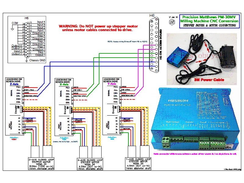
Recently we have some reports on Wiring Questions on our Reprap Stepper Motors. And we have a look on it and find that it is not individual. The questions is that on motor side the color of the lead wires are Red(A+), Yellow(B+), Grey(A-) and Green(B-) in turn. As usual, on the other side the stepper driver B-, B+, A+ and A- but the Mark on A4988 Driver can make you confused. See the following: From the lower 1B, 1A, 2A and 2B. The question is that 1B and 1A is one phase(one coil) and 2A and 2B is the other phase(one coil).
http://www.pololu.com/catalog/product/1182 A4988 Driver To solve the wiring question using our stepper motor, you need to exchange the Yellow(the 2nd) and Grey(the 3rd) on the motor side or the other side of the lead wire(Plug to Stepper Driver).
RobotDigg welcome your order of our NEMA17 60mm 0.65N.m Stepper Motor and Threaded Rod Nema17 Stepper Motor with strong Tr8*8 Leadscrew.
Back to Nema23, is using a bigger size stepper motor means more powerful your 3d printer will be? The answer is absolutely NOT. RobotDigg find that most of 3d printer makers are trying to buy a longer body stepper motor. But that’s only one side of the solution of higher torque output. The other side is the Stepper Driver. A4988 stepper driver is very popular in 3d printing industry, it’s a good driver which can drive up to 2A. But when you use it to drive a long body stepper motor Nema17 48mm or 60mm Stepper when you give it 12V power supply, you find that you still have the question of low torque output. How to figure it out? Increase the power supply. You may say you have a 12V power system, so increase the set Current, at least equal to the Rated Current of the stepper motor you have in your 3d printer system. OK, we are a little far. Why a Nema23 Stepper is not that ideal for your 3d printer? As we know, Nema23 is very popular in CNC machines. We also can see that a CNC machine usually has 24V power supply. Set the current of the stepper driver the Rated Current of the stepper motor. A stepper motor with rated current 1.5A, if you give only 1A, the holding torque could be half or even lower, especially when increase the speed and heat generation after a long time run. Is there a Nema23 stepper motor good for 3d printer and can be drived by A4988 stepper driver? The answer is yes. RobotDigg are glad to show you a Nema23 stepper of this kind in the near future. Instead of a Nema23, are there a Nema17 Stepper Motor can meet my need? A Nema17 60mm with Rated Current 1.5A(within 2A, set your A4988 stepper driver at 1.2A or 1.5A won’t hurt the stepper driver. But if you set the stepper driver at 2A, it cann’t run long time, the stepper motor may pause.), a Holding Torque 65N.cm 92oz.in which is really with enough power for your 3d printers.
Now we know the stepper motors required for our project we can match them to a suitable CNC controller. The controller converts the g-code we’ve created and sends step pulses to the stepper motors. It also takes input signals from the machine such as limit switches and E-stops.
So there are 3 things we need to know:
Number of Axes. So usually 3 for routers and 4 for a foam cutter Current and voltage we need to supply to the stepper motors How do we intend to connect the computer to the CNC controller Number of Axes CNC routers can use 3 or 4 axis controllers. There is only 3 planes of movement X, Y and Z but some designs use two stepper motors on one axis. My OX CNC router uses two NEMA 23 on the Y-Axis as its a gantry type router. Some move the table bed for the Y-Axis on sliders and only need 1 motor for the Y-Axis. Like a 3d printer bed.
Y-Axis complete and running very smooth
Foam cutters need 4 axes to allow the hot wire to move in any direction on 4 planes usually X,Y,U and V.
Generally, you are going to need at last NEMA23 from 175oz/in upwards unless your machine is very small such as a CNC engraver. These are quite often used for making Printed Circuit Boards(PCB) and if you check the description they will say only for soft materials.
For routers, the cutting material plays a big part in our decision. Harder materials will need a more powerful stepper because the cutting bit is being driven into the material.
The WorkBee from Ooznest in the UK which is based on the OpenBuilds design. It uses NEMA23 of 175 oz/in. If you check some of the offerings on eBay for 6040 CNC routers you’ll quite often see in the description 57 size motors, which is the metric equivalent of 2.3 inches or NEMA23’s and these usually come with 175-200oz-in motors
If you intended to cut very hard materials then high torque steppers motors will be required usually around 300-400 oz/in and you may need to go up to NEMA34 and you will need a strong frame to support that.
Step motors are widely used in automation due to their high resolution, precision positioning, minimal control electronics, and low cost. As an open loop system, traditional step motors are driven without the need for sensors to feed information back to a controller; however, the open loop configuration of step motors has challenges.
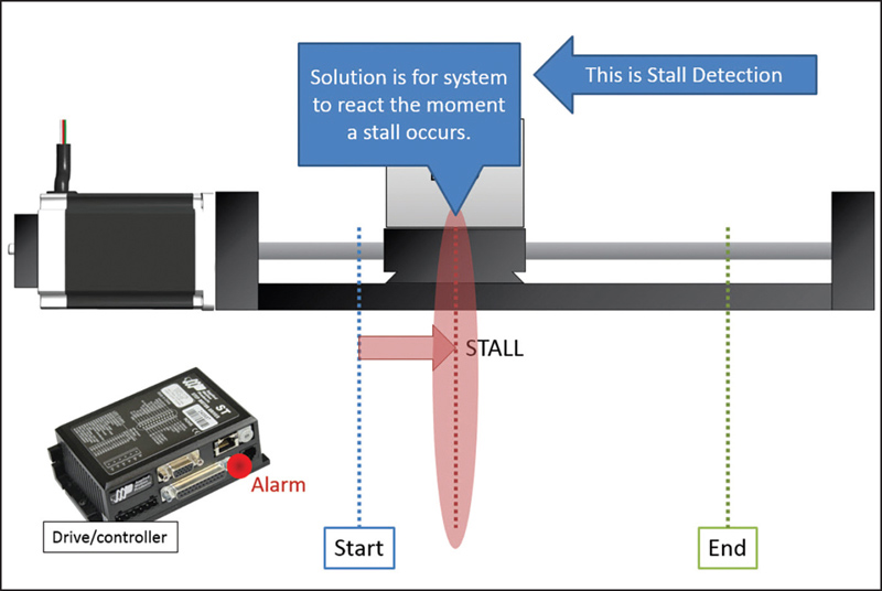
Position Verification — When pushed beyond its limits, a step motor will stall before reaching the endpoint. This event typically occurs when motors are not adequately specified for high-cycle applications. An encoder can provide position feedback at the end of the motion profile, indicating if the step motor stopped before reaching the end position. The controller compares the encoder counts that define the actual motor position to the target motor position at the end of a move to determine if there is a difference. If the encoder counts don’t match to the actual motor position, a corrective move or motion profile is calculated and executed.
Stall Detection — Stall detection notifies the user/system/machine as soon as a motor stall occurs, eliminating the uncertainty of whether or not the motor reached its target position. A more advanced function than position verification, stall detection (Figure 2) enables the controller to compare the registers of the encoder counts and target motor position on a continuous basis instead of just at the end of the move.
Stall Prevention— While greatly increasing system functionality, stall detection does not inherently improve step motor performance; it still requires the operator to perform a corrective move and re-reference the axis to the home position. Stall prevention, on the other hand, dynamically and automatically adjusts the move profile to prevent a stall, enabling the motor to operate with constant torque to get into an accurate end position without stalling.
Servo Control and Increased Motor Torque — Using stepper motor encoder feedback to servo-control, a step motor increases motor torque for greater dynamic performance. With peak torques up to 50% higher than the rated holding torque of the motor, the servo-controlled step motor system can operate at higher acceleration rates and with higher throughput for faster machine cycles.
When using a stepper motor, integrating an incremental encoder is relatively straightforward. Still, there are some general guidelines to consider.
Incremental encoders (like any stepper motor encoder) all function as part of a feedback system — providing closed-loop operation. Using information from the encoder, the drive system alters motor operation.
However, incremental encoders don’t keep track of position once power is lost. They also need a reference position to return to every time upon startup.
Keep this in mind when using and driving a stepper motor, because the machine design must set to a reference position when using incremental encoders.
Incremental encoders are often useful when speed control requirements are part of a system. If there’s less concern over the position of the shaft — and more of a concern over how fast it is moving — then the fact that incremental encoders don’t track position once off is less critical. In fact, here their simple operation and low price benefit the design.
Incremental encoders keep track of speed where only the difference between two positions is necessary.
There are a few different methods to mount an encoder to a stepper motor. Each of them is useful for various situations, and the choice depends on the motion system.
Incremental encoders with shaft mounting … A coupling connects the encoder to the shaft. This creates mechanical and electrical isolation, but also adds cost because the coupling is an extra part and because this method requires a longer motor shaft.
Incremental encoders with a hub or hollow-shaft setup … The encoder directly mounts to the motor using a spring-loaded tether. This is a design that is easy to install and requires no alignment. The only caveat is that this geometry requires careful electrical isolation.
Incremental encoders with a bearingless or ring mount … Here, the sensor is in the form of a ring that mounts to the motor’s surface. A wheel mounts to the motor’s shaft. There are useful for heavy-duty applications.
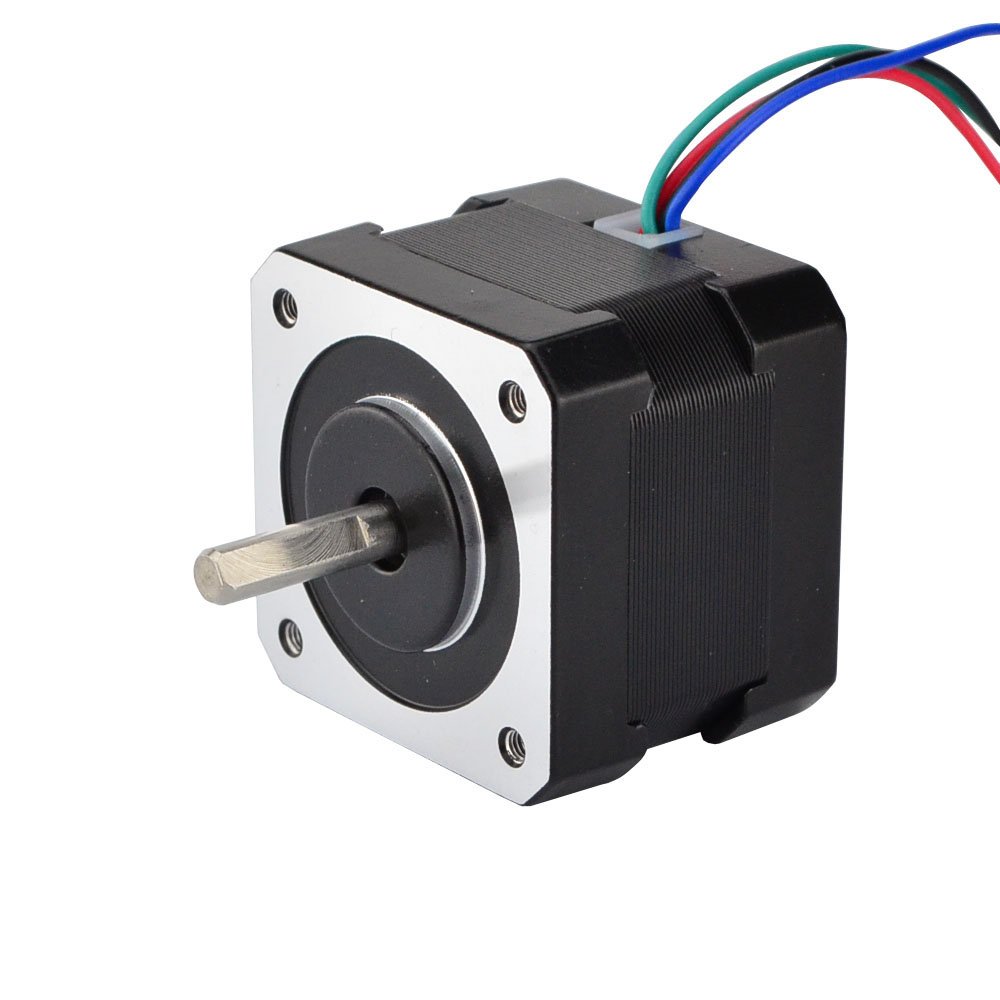
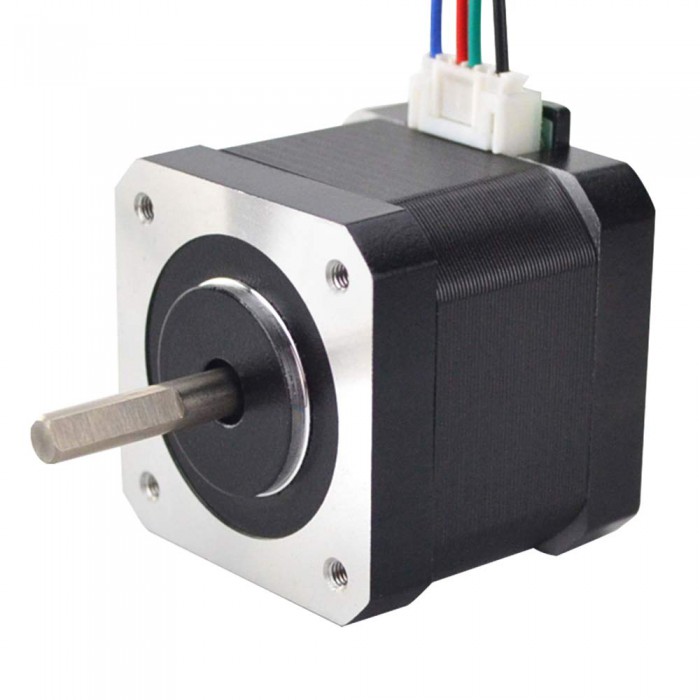
Nema 17 motor is not standard for electrical characteristics of the stepper motor. It is just faceplate and mounting holes standard to make it easier to interchange motors. Most likely you have to check from the specification that what is rated current for that motor and is it unipolar or bipolar one. Choose driver based on that.
Note: Drive can always be more powerful than the motor, but you have to limit your current from the drive side. It’s also possible to use chopper drives with the less current rating, but then your motor runs underpowered.
But one can definitely make assumptions on the motor size that NEMA 17 could use 1A – 2A current and NEMA 23 motor could use around 2A – 5A current.
Final words This articles scope was to make a high-level overview of how to drive a stepper motor. I hope I delivered and you have now a better understanding of this topic and can start experimenting.
Now the real fun and learning begins.
There is a lot more than these basic concepts I introduced. There will be problems with vibration, torque, cooling motors, choosing hardware, missing steps, calculating steps and configuring software. Stepper motor projects are prone to problems because of all dependencies in the chain. Starting from hardware or power to bad configuration or just wrong program. Basic debugging skills are very handy here and it helps to have extra components to switch in case of hardware malfunction.
Did I answer all basic questions? Or I missed some crucial concept that left you wondering? Let me know about it in the comments. I would be grateful to know so I can improve this article.